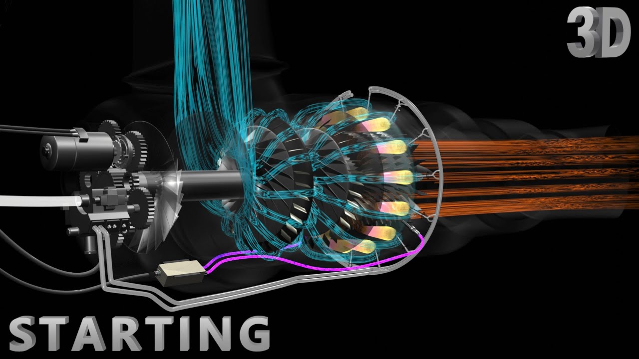
How Jet Engine Works | Part 2 : Outputs
Summary
TLDRThis video delves into the intricate workings of the Boeing 777's engine systems. It explains how thrust is controlled, the importance of engine-generated power for electrical, hydraulic, and pneumatic systems, and the roles played by various components. Key topics include the use of the IDG for stable electrical output, the left engine powering hydraulic systems, and the engine's role in pneumatic air supply. The video also covers the anti-icing system, vital for preventing ice formation on engine inlets during harsh weather conditions. All these systems ensure smooth operation of the aircraft across various conditions.
Takeaways
- 😀 The thrust of the engine is controlled by the thrust lever, which adjusts the fuel flow to match the desired engine thrust.
- 😀 The aircraft's electrical power is distributed through two main electrical buses, with the APU generator supplying power to both buses when needed.
- 😀 If there is a loss of electrical power from the engine, the GE90's backup generator can supply power to essential aircraft loads, with a converter stabilizing the output.
- 😀 The aircraft's electrical system requires a constant 415Hz frequency, which is maintained by the Integrated Drive Generator (IDG) despite changes in engine RPM.
- 😀 The hydraulic power for the aircraft is pressurized by the engine-driven hydraulic pump, which supports various flight control surfaces and systems.
- 😀 The engine provides pneumatic power by bleeding air from the high-pressure compressor to meet the demands of various aircraft systems, like air conditioning and anti-icing.
- 😀 The Engine Bleed Air system is controlled by the Aircraft Supply Cabin Pressure Controller (ASCPC), which manages bleed air pressure and temperature.
- 😀 If the IDG malfunctions, the system uses a disconnect switch to prevent further damage, but the GE90's backup generator can still support essential power needs.
- 😀 The engine anti-ice system uses air from the high-pressure compressor to prevent ice buildup on the engine inlet cowl in cold weather conditions.
- 😀 The system automatically regulates the anti-ice valve based on inputs from an ice detector, ensuring safe operation during adverse weather conditions.
Q & A
How is the thrust from the GE90 engine controlled?
-The thrust is controlled by advancing the thrust lever, which sends a signal to the electronic engine control (EEC). The EEC commands the hydro-mechanical unit (HMU) to adjust the fuel flow rate to the combustion chamber, increasing the engine's thrust accordingly.
What happens when the thrust lever is moved from idle to a higher position?
-When the thrust lever is moved from idle, it signals the EEC to adjust the fuel flow rate through the HMU. The HMU increases the fuel flow to the combustion chamber, matching the engine's thrust to the lever settings.
How does the electrical system ensure stable power supply despite varying engine RPM?
-The electrical system uses an Integrated Drive Generator (IDG), which combines a constant speed drive with an AC generator. This setup ensures the generator operates at a constant speed, maintaining a steady 415 Hz output regardless of the changing engine RPM.
What role does the load management system play in the electrical power supply?
-The load management system prioritizes essential electrical loads on the aircraft. It sheds non-essential loads (such as galleys and entertainment systems) if only one power source is available. When both the APU generator and engine-powered IDG are operational, the system restores power to all loads.
What happens if the IDG malfunctions?
-If the IDG malfunctions, the 'drive light' illuminates, and the disconnect switch is used to decouple the IDG from the gearbox. If this occurs, the aircraft loses electrical power from the affected engine, though the GE90 has a backup generator to provide power for essential loads.
How does the backup generator work on the GE90?
-The backup generator on the GE90 doesn't have a constant speed drive. Its output frequency varies with engine RPM. Therefore, the output is first sent to a converter, which changes the variable frequency to a stable 415 Hz, supplying power to essential aircraft loads only.
What is the function of the hydraulic pump on the left engine?
-The engine-driven hydraulic pump on the left engine pressurizes the hydraulic fluid to 3000 PSI, delivering it to the aircraft's hydraulic components such as the left engine thrust reversers, left aileron, flight spoilers, elevators, and rudder.
What systems are powered by the aircraft's hydraulic system?
-The hydraulic system powers the left engine thrust reversers, left aileron, left flaps, some flight spoilers, left and right elevators, and the rudder. Other components are powered by the center and right hydraulic systems.
How does the pneumatic power system work in the aircraft?
-The engine bleed air is controlled by the Air Supply Cabin Pressure Controller (ASCPC), which ensures that there is no pressure in the pneumatic ducts before the engine bleed is used. The ASCPC opens valves to allow the bleed air to flow, supplying various aircraft systems like air conditioning, hydraulic reservoir pressurization, and anti-icing.
What is the purpose of the engine's anti-icing system?
-The engine's anti-icing system prevents ice formation on the engine's inlet cowl in adverse weather conditions. The system uses pneumatic bleed air from the compressor stage to circulate hot air to the leading edge of the inlet, stopping ice buildup.
Outlines

This section is available to paid users only. Please upgrade to access this part.
Upgrade NowMindmap

This section is available to paid users only. Please upgrade to access this part.
Upgrade NowKeywords

This section is available to paid users only. Please upgrade to access this part.
Upgrade NowHighlights

This section is available to paid users only. Please upgrade to access this part.
Upgrade NowTranscripts

This section is available to paid users only. Please upgrade to access this part.
Upgrade NowBrowse More Related Video

How Jet Engine Works | Part 1 : Starting
Aircraft Doors and Door assist ATA 52
How Auxiliary Power Units Work | Part 1 : Starting

17 ATPL Training Gas Turbine Engines #17 Ignition Systems

What Really Happened to the Missing Malaysian Airlines Flight 370

Planespotting 101: How To Identify Each Major Commercial Aircraft Type
5.0 / 5 (0 votes)