First angle and Third angle method of projections
Summary
TLDRIn this technical drawing tutorial, the instructor explains the difference between first-angle and third-angle projection symbols. The video also demonstrates how to draw a frustum of a cone using these projection methods, beginning with a circle and a square. The instructor provides clear step-by-step guidance on setting angles and dimensions, offering a standard approach used globally for technical drawings. Additionally, the video briefly covers the concept of quadrants and their relevance to projection methods, aiming to help viewers grasp essential concepts in technical drawing.
Takeaways
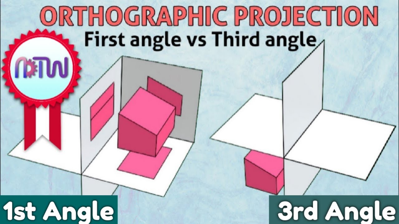
- 😀 The video explains the difference between first-angle and third-angle projection methods in technical drawing.
- 😀 First-angle projection places the front view at the top and the left view to the right.
- 😀 Third-angle projection places the front view at the bottom and the left view to the left.
- 😀 The object shown in the video is a frustum of a cone, and the focus is on how to project it using both methods.
- 😀 The front view of the frustum in first-angle projection is a trapezium, and the left view is displayed on the left.
- 😀 In third-angle projection, the front view is also a trapezium, but the left view is placed on the left side of the drawing.
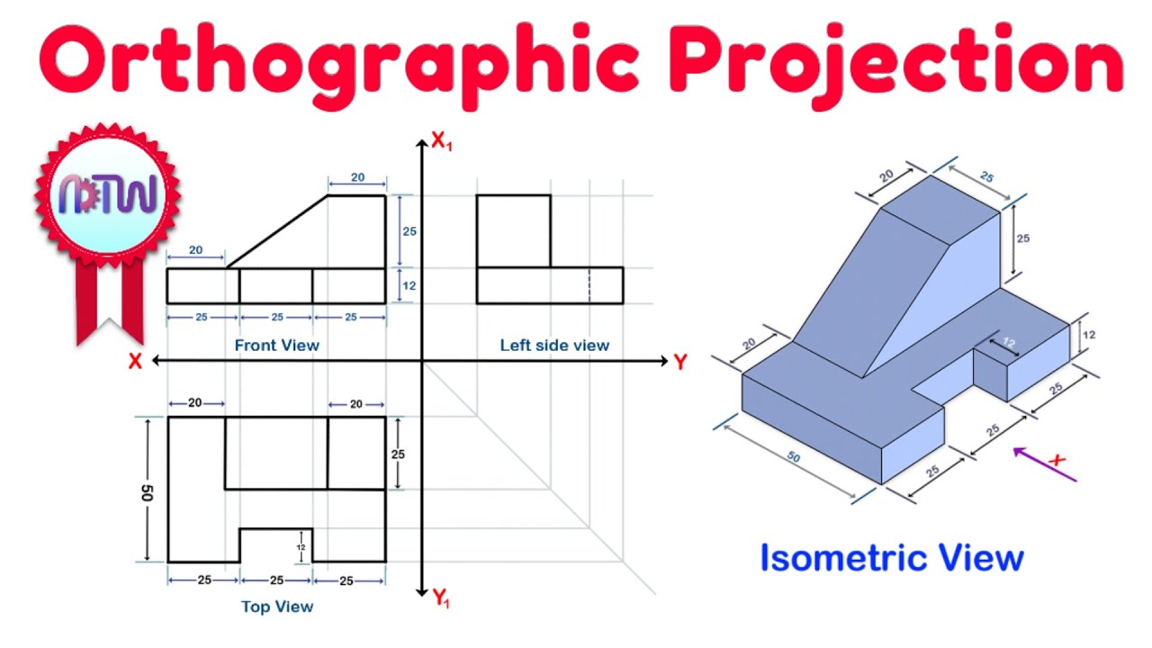
- 😀 To draw the frustum, start with a circle of diameter 50 mm and draw a square with a side of 50 mm in the front view.
- 😀 Standard drawing practice involves projecting a circle with a diameter of 50 mm inside the square in the front view.
- 😀 A 15-degree angle is applied from both sides of the square to form the trapezoidal shape for the front view of the frustum.
- 😀 The video briefly mentions the concept of the four quadrants, indicating that the first and third quadrants are relevant to the two projection methods.
Q & A
What is the main focus of the video?
-The video focuses on explaining the difference between first angle and third angle projection symbols in technical drawing.
What is the first angle projection symbol?
-The first angle projection symbol is typically represented with a specific geometric shape, which is used to indicate the first angle method of projection in technical drawing.
What is the third angle projection symbol?
-The third angle projection symbol is a different geometric shape, used to denote the third angle method of projection in technical drawing.
How is a frustum of a cone used in the explanation?
-A frustum of a cone is used to demonstrate how the front and side views change when looking at it from different angles, specifically the first and third angle methods of projection.
What shape is used to represent the front view of the frustum of a cone?
-In the first angle method of projection, the front view of the frustum of a cone is represented as a trapezium.
How does the left side view of the frustum of a cone appear in first and third angle projection?
-In first angle projection, the left side view appears on the left side of the projection, while in third angle projection, it appears on the right side.
What is the standard dimension used for projection in the example?
-In the example, the standard dimension for the circle is a diameter of 50 units.
How do you draw the square for the front view?
-To draw the square for the front view, the side length of the square should be equal to the diameter of the circle, in this case, 50 units.
What is the significance of the 15-degree angle in the drawing?
-The 15-degree angle is a standard dimension used globally to ensure consistency in technical drawings. It helps to project the correct shape and size in the projection views.
What is the relationship between the first and third quadrants in the context of projection?
-In the first quadrant, the first angle projection method is used, and in the third quadrant, the third angle projection method is applied.
Outlines

This section is available to paid users only. Please upgrade to access this part.
Upgrade NowMindmap

This section is available to paid users only. Please upgrade to access this part.
Upgrade NowKeywords

This section is available to paid users only. Please upgrade to access this part.
Upgrade NowHighlights

This section is available to paid users only. Please upgrade to access this part.
Upgrade NowTranscripts

This section is available to paid users only. Please upgrade to access this part.
Upgrade NowBrowse More Related Video

Orthographic Projection_An Introduction_Engineering Drawing_Engineering Graphics_English
First angles vs Third angle method | Orthographic projections animation
Orthographic Projection from isometric view in Engineering drawing
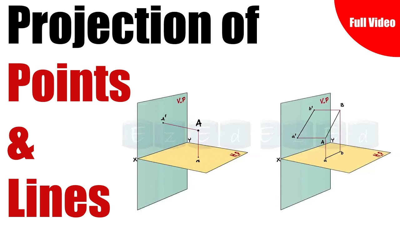
Full Video- Projection Of Points & Lines

ORTHOGRAPHIC DRAWING EXAMPLE

Slope, Line and Angle Between Two Lines |Analytic Geometry|
5.0 / 5 (0 votes)