Servo Motors, how do they work?
Summary
TLDRThis video tutorial explores the intricacies of servo motors, crucial in precision engineering for their ability to convert electrical energy into mechanical movement with exact control. It delves into the differences between closed and open loop servos, explains torque ratings, and demonstrates how to program a servo using an Arduino and a potentiometer. The video also highlights a sponsor, Private Internet Access, offering a VPN service for online privacy and security.
Takeaways
- 😀 A servo motor is utilized in precision engineering for its ability to convert electrical energy into mechanical energy with precise control.
- 🛠️ Servo motors are often found in robotics, automation, and remote control cars due to their capacity for exact positioning.
- 🔁 Unlike a standard DC motor, a servo motor does not rotate continuously; it receives signals that dictate the extent of its rotation, typically within a 180-degree range.
- 🔁 There are two types of servo motors: closed-loop (with a physical stop at 180 degrees) and open-loop (capable of 360-degree rotation), with the closed-loop type being more common for its superior control.
- ⚖️ The torque of a servo motor is indicated by a weight value, which represents the force it can apply to a lever, commonly measured in kilogram centimeters or ounce inches.
- 🔌 The servo motor's performance is influenced by the voltage supplied, with higher voltages leading to increased torque and faster rotation speeds.
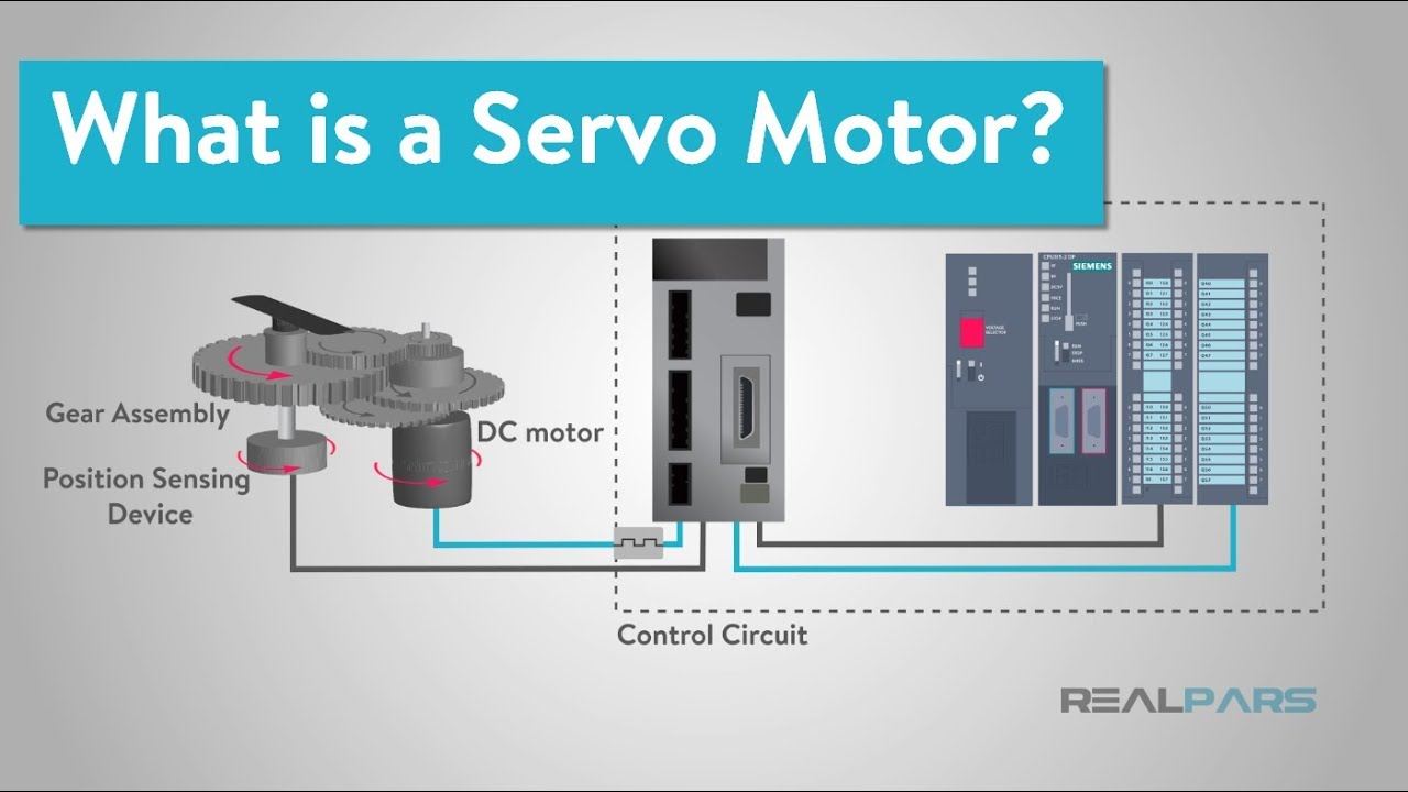
- 🔍 The internal components of a servo motor include a DC motor, gears, bearings, and a potentiometer, which work together to achieve the desired torque and speed conversion.
- 💻 A controller sends pulse width modulation signals to the servo motor to specify its position, with the pulse width determining the extent of the motor's rotation.
- 🔄 The potentiometer within the servo motor provides feedback on its position by changing resistance as it rotates, which the circuit board uses to ensure the motor is in the correct position.
- 🛠️ The tutorial demonstrates how to program an Arduino to control a servo motor using a potentiometer, showcasing a practical application of servo motors in interactive projects.
Q & A
What is a servo motor and where is it commonly used?
-A servo motor is a type of motor used in precision engineering applications that converts electrical energy into mechanical energy. It is commonly used in robotics, automation, and the steering of remote control cars.
How does a servo motor achieve precise control?
-A servo motor achieves precise control through the use of internal electronics and mechanical gears. It receives signals that tell the motor exactly how far to rotate, typically within a range of 180 degrees, but can be smaller or larger depending on the model.
What is the difference between closed loop and open loop servo motors?
-Closed loop servo motors have a pin inside to physically stop the motor from rotating further, providing the best control and are more commonly used. Open loop servo motors can rotate a full 360 degrees without such a physical stop and are less common.
What does the weight value on the side of a servo motor represent?
-The weight value on the side of a servo motor represents the torque of the motor, or how much force it can apply. It is measured in kilogram centimeters or ounce inches.
How does the voltage affect the performance of a servo motor?
-The higher the voltage applied to a servo motor, the higher the torque and the stronger the motor will perform. However, there are limits, and the motor will stall if it exceeds these limits.
What is the relationship between the voltage and the speed of a servo motor?
-The higher the voltage applied to a servo motor, the faster it will rotate. The speed is measured in seconds taken per 60 degrees of rotation.
What are the main components inside a servo motor?
-Inside a servo motor, there are gears, bearings, a DC motor, and a circuit board. The gears are part of a compound gear train that converts high-speed low torque into low-speed high torque.
How does a potentiometer work in a servo motor?
-A potentiometer in a servo motor acts as a variable resistor. As the final gear rotates, it rotates the potentiometer, changing the resistance. The circuit board reads this change to know the position of the output.
What is pulse width modulation and how is it used in controlling a servo motor?
-Pulse width modulation (PWM) is a method of encoding information in the width of pulses of voltage sent down a wire. In servo motors, the width of the pulse determines the position of the motor, with wider pulses moving it to one extreme and narrower pulses to the other.
How can an Arduino be used to control a servo motor?
-An Arduino can be used to control a servo motor by sending it PWM signals through one of its digital pins. The Arduino can be programmed to read an input, like a potentiometer, and send the appropriate PWM signal to the servo motor to control its position.
What is the purpose of the comparator in the servo motor's circuit board?
-The comparator in the servo motor's circuit board compares the voltage from the potentiometer to the voltage of the controller signal. If there is a difference, it sends a signal to the motor to turn until the difference is minimized, ensuring the motor is in the correct position.
Outlines

This section is available to paid users only. Please upgrade to access this part.
Upgrade NowMindmap

This section is available to paid users only. Please upgrade to access this part.
Upgrade NowKeywords

This section is available to paid users only. Please upgrade to access this part.
Upgrade NowHighlights

This section is available to paid users only. Please upgrade to access this part.
Upgrade NowTranscripts

This section is available to paid users only. Please upgrade to access this part.
Upgrade NowBrowse More Related Video

How Stepper Motors Work - Electric motor

Difference between Stepper and Servo Motor | Servo और Stepper Motor कैसे काम करता है ?
Motor VS Generator VS Alternator || How Generator, Motor And Alternator Works || In Hindi
What is a Servo Motor and How it Works?

How does an Electric Motor work? DC Motor explained

Jak funguje elektromotor – NEZkreslená věda III
5.0 / 5 (0 votes)