How does an Electric Motor work? DC Motor explained
Summary
TLDRIn this educational video, Paul from engineeringmindset.com explores the fundamentals of DC motors, which convert electrical energy into mechanical energy for applications in power tools, toy cars, and cooling fans. He details the motor's components, including the stator, rotor, commutator, and brushes, and explains how they work together to create rotation. Paul also covers basic electricity concepts, the role of permanent magnets, and the significance of Fleming's left-hand rule in determining the direction of force on the coils. The video is a comprehensive guide for understanding the inner workings of DC motors and their practical applications.
Takeaways
- 🔌 DC motors convert electrical energy into mechanical energy and are used in various applications like power tools, toy cars, and cooling fans.
- 🏗️ The basic components of a DC motor include a metal casing (stator), a rotor with laminated disks and coil windings, a shaft, and a commutator.
- 🧲 The motor contains permanent magnets that create a strong magnetic field through the rotor, essential for the motor's operation.
- 🔋 The commutator is a segmented ring that helps control the timing and polarity of the magnetic field, enabling the motor to rotate.
- 🔌 The brushes and brush arms complete the electrical circuit by rubbing against the commutator segments, allowing current to flow to the coils.
- 🔋 The rotor's laminated disks reduce eddy currents, which can decrease motor efficiency, by providing electrical insulation between each disk.
- 🔧 Fleming's left-hand rule is used to determine the direction of force on a coil when it interacts with a magnetic field, crucial for understanding motor rotation.
- 🔄 The motor's rotation is achieved through the interaction of the electromagnetic fields created by the current-carrying coils and the permanent magnets.
- 🔀 Reversing the power supply or the current direction will reverse the forces acting on the coils, thus changing the direction of motor rotation.
- 📚 Understanding the fundamentals of electricity, such as electron flow, current, voltage, and magnetic fields, is essential for comprehending how DC motors work.
- 🔍 The script encourages viewers to think about where they have seen DC motors used and to share their project ideas in the comments section.
Q & A
What is the primary function of a DC motor?
-The primary function of a DC motor is to convert electrical energy into mechanical energy.
What are some common applications of DC motors?
-DC motors are commonly used in power tools, toy cars, and cooling fans.
What are the main components of a DC motor?
-The main components of a DC motor include the stator, rotor, commutator, brushes, and permanent magnets.
What is the role of the stator in a DC motor?
-The stator is the metal protective casing that houses the motor and provides a stationary structure for the rotor to spin within.
What is the purpose of the rotor in a DC motor?
-The rotor is made from laminated disks with T-shaped arms and coil windings, which when energized, interact with the magnetic field to produce rotation.
How does the commutator in a DC motor work?
-The commutator is a segmented ring that electrically isolates different plates and helps to switch the connections of the coil windings as the rotor turns, maintaining continuous rotation.
What are the brushes in a DC motor and what do they do?
-The brushes are conductive contacts that rub against the commutator segments to complete the electrical circuit, allowing current to flow through the motor.
Why do DC motors use coils instead of straight wires to create a magnetic field?
-Coils are used because when wires are wrapped into a coil, the individual electromagnetic fields combine to create a much larger and stronger magnetic field.
What is the significance of laminating the rotor disks in a DC motor?
-Lamination of the rotor disks helps to reduce eddy currents, which can decrease the motor's efficiency by causing energy loss due to induced electromagnetic forces.
What is Fleming's left-hand rule and how is it used in DC motors?
-Fleming's left-hand rule is a method to determine the direction of force on a current-carrying conductor in a magnetic field. It is used in DC motors to understand the interaction between the electromagnetic field of the coils and the magnetic field of the permanent magnets, which results in the motor's rotation.
How does reversing the battery in a DC motor affect its operation?
-Reversing the battery changes the direction of the current flowing through the motor, which in turn reverses the forces acting on the coils and changes the direction of the motor's rotation.
Outlines

This section is available to paid users only. Please upgrade to access this part.
Upgrade NowMindmap

This section is available to paid users only. Please upgrade to access this part.
Upgrade NowKeywords

This section is available to paid users only. Please upgrade to access this part.
Upgrade NowHighlights

This section is available to paid users only. Please upgrade to access this part.
Upgrade NowTranscripts

This section is available to paid users only. Please upgrade to access this part.
Upgrade NowBrowse More Related Video

Heritage Tourism / Meaning, Activities and Benefits of Heritage Tourism / Ecotourism Journey
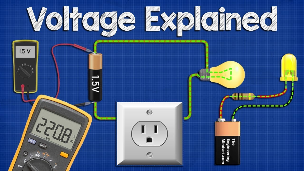
Voltage Explained - What is Voltage? Basic electricity potential difference

Should I Pursue Biblical Counseling as a Career? | Ask Paul Tripp (029)
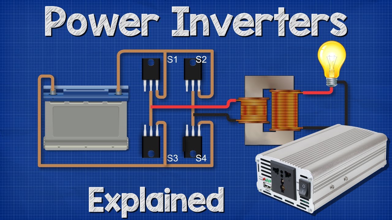
Power Inverters Explained - How do they work working principle IGBT
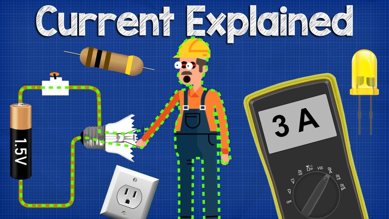
What is CURRENT– electric current explained, electricity basics

Practice 2 - Developing and Using Models
5.0 / 5 (0 votes)