Arduino - Aula 22 - Experimento 9 - Motor elétrico
Summary
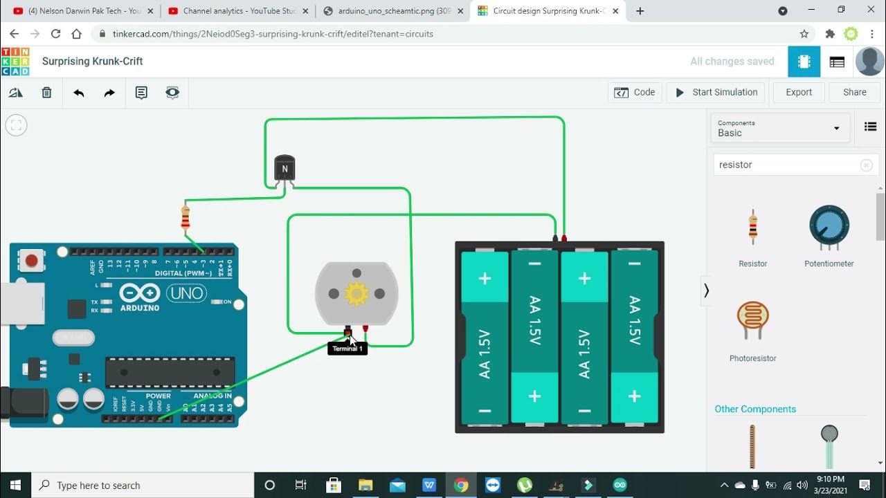
TLDRIn this detailed Arduino tutorial, the instructor demonstrates how to build a circuit to control a 12V DC motor using an Arduino board, a transistor, resistors, and a push button. The step-by-step guide covers both the hardware setup, including wiring the button, motor, and transistor, and the software code that reads the button's state to turn the motor on and off. This beginner-friendly lesson introduces key concepts in electronics and programming, making it an excellent starting point for learning to control motors with Arduino.
Takeaways
- 😀 The tutorial demonstrates how to set up a 12V DC motor with Arduino, using a transistor and push button to control it.
- 😀 You need several components, including an Arduino board, DC motor, transistor (TP121), resistors (330Ω and 10kΩ), and a push button.
- 😀 The motor is powered by a 12V adapter, and the transistor acts as a switch to control the motor's current.
- 😀 The push button is used to control the motor's state by sending a signal to the Arduino (via pin 13).
- 😀 A 330Ω resistor is used to limit current to the transistor's base, protecting the circuit from excessive current.
- 😀 The 10kΩ resistor is connected to the button to protect the circuit by preventing short circuits when the button is pressed.
- 😀 The transistor’s base is connected to Arduino pin 6, which sends a signal to either turn the motor on or off depending on the button's state.
- 😀 The Arduino code defines a 'control' variable that checks if the button is pressed (LOW) or not (HIGH).
- 😀 If the button is pressed, the Arduino sends a HIGH signal to pin 6, turning on the motor through the transistor.
- 😀 The tutorial includes both a simulation and a real-world setup, where pressing the button makes the motor rotate and releasing it stops the motor.
Q & A
What components are needed to build the circuit for controlling a DC motor in the tutorial?
-The components required are: an Arduino board, a breadboard, a 330-ohm resistor, a 10k-ohm resistor, a push button, a TP121 transistor, a 12V motor, a power supply, and wires.
What is the role of the 10k-ohm resistor in the circuit?
-The 10k-ohm resistor is used to protect the circuit by ensuring proper current flow and preventing excess current that could damage components.
Why is a TP121 transistor used in the circuit?
-The TP121 transistor is used to amplify the current from the Arduino, allowing it to control the 12V motor which requires higher current than the Arduino can provide directly.
How does the push button work in the circuit?
-The push button is connected to pin 13 on the Arduino. When pressed, it sends a signal to the Arduino to trigger the transistor, which controls the motor's operation.
What happens when the button is pressed in the circuit?
-When the button is pressed, it sends a signal to the Arduino's digital input (pin 13). The Arduino then activates pin 6 to turn on the transistor, allowing current to flow through the motor and making it spin.
How is the motor powered in the circuit?
-The motor is powered by a 12V power supply, which is connected to the motor and transistor. The transistor acts as a switch, allowing the motor to receive the necessary current from the power supply.
Why is a power supply used in the circuit and what is its voltage?
-A power supply of 12V is used to provide sufficient power to the motor, as it requires a 12V input. The Arduino alone cannot supply enough power to run the motor.
What is the function of the 'digitalWrite' command in the Arduino code?
-'digitalWrite' is used to set a specific digital pin on the Arduino to either HIGH (on) or LOW (off). In this case, it controls whether the motor should be on or off by sending a signal to the transistor through pin 6.
What is the significance of the conditional check in the Arduino code?
-The conditional check in the code determines whether the button is pressed. If the button is pressed (input is 0), the Arduino sends a HIGH signal to pin 6 to turn on the motor. If the button is not pressed (input is not 0), it sends a LOW signal to turn off the motor.
How does the transistor work in conjunction with the Arduino to control the motor?
-The transistor amplifies the current from the Arduino. When the Arduino sends a signal to the transistor's base, it allows a larger current to flow from the power supply to the motor, thus enabling the motor to run.
Outlines

This section is available to paid users only. Please upgrade to access this part.
Upgrade NowMindmap

This section is available to paid users only. Please upgrade to access this part.
Upgrade NowKeywords

This section is available to paid users only. Please upgrade to access this part.
Upgrade NowHighlights

This section is available to paid users only. Please upgrade to access this part.
Upgrade NowTranscripts

This section is available to paid users only. Please upgrade to access this part.
Upgrade NowBrowse More Related Video

motor speed controller with arduino in tinkercad | motor speed controller with PWM in tinkercad

Como usar PINO DIGITAL de ENTRADA no arduino - Curso Gratuito pelo Tinkercad - Aula 2

Arduino Solar Tracker | Science Project

Rangkaian Driver Motor Dengan Konfirgurasi H-BRIDGE MOSFET

Arduino Lesson 2 - digitalRead & digitalWrite

Bootloader and upload to Atmega328P-AU
5.0 / 5 (0 votes)