Boolean Logic & Logic Gates: Crash Course Computer Science #3

CrashCourse
8 Mar 201710:07

Summary

TLDRIn this episode of Crash Course Computer Science, Carrie Anne introduces the concept of abstraction in computing, explaining how binary representation with its two states (on and off) is used to represent true and false values. She discusses the evolution of computers from electromechanical devices to electronic ones with transistors, which can handle binary data. The video also covers Boolean Algebra, its origin with George Boole, and the fundamental operations: NOT, AND, and OR. Carrie Anne demonstrates how these operations can be physically constructed using transistors as switches, creating NOT gates, AND gates, and OR gates. She then introduces the concept of an Exclusive OR (XOR) gate, which is true only when one of the inputs is true. The episode emphasizes the importance of moving up the ladder of abstraction, allowing engineers and programmers to work with logic gates and larger components without needing to understand the intricate details of the underlying transistors and electrical signals.

Takeaways

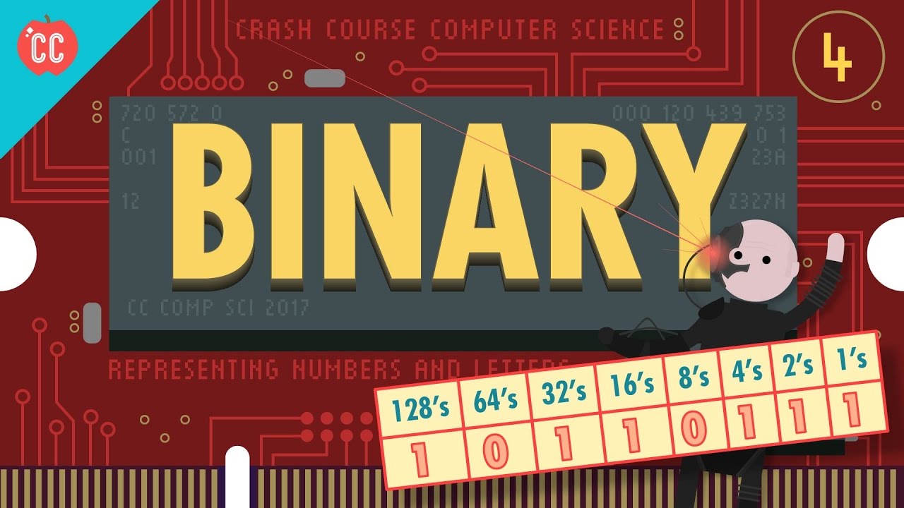
  • 📈 **Binary Representation**: Computers use binary (1's and 0's) to represent data, which is derived from the two states of electricity (on and off).
  • 🛠️ **Transistors as Switches**: Transistors can act as electrically controlled switches, allowing for the creation of basic logic gates that form the foundation of computer logic.
  • 🔍 **Binary Advantage**: Binary's simplicity helps in minimizing signal mixing issues, especially under conditions like low battery or electrical noise.
  • 📚 **Boolean Algebra**: An existing branch of mathematics that deals with true and false values, which is integral to computer science and logic operations.
  • 🔁 **Fundamental Boolean Operations**: NOT, AND, and OR are the three basic operations in Boolean Algebra, essential for building logic gates.
  • 🚿 **Transistors and NOT Gates**: A NOT gate can be constructed using a single transistor, where the input and output states are inverses of each other.
  • 🔗 **AND Gate Construction**: An AND gate requires two transistors working together, allowing current to flow only when both inputs are true.
  • 🔄 **OR Gate Configuration**: An OR gate, made with transistors in parallel, produces an output when at least one of the inputs is true.
  • 🔶 **Exclusive OR (XOR) Gate**: The XOR gate is similar to an OR gate but returns false when both inputs are true, representing a key component in computing.
  • 🛑 **Abstraction in Computing**: Engineers often work at higher levels of abstraction, using logic gates and larger components to design processors, rather than focusing on individual transistors.
  • 🤔 **Programmers and Logic**: Most computer programmers don't need to consider the physical implementation of logic in transistors and semiconductors when writing code.
  • 🏗️ **Building Complex Logic**: With just the basic logic gates, complex logic statements and computations can be constructed, demonstrating the power of these foundational components.

Outlines

00:00

😀 Introduction to Binary and Boolean Algebra

Carrie Anne introduces the concept of abstraction in computer science, explaining the shift from visible mechanical components to electronic systems. She discusses the binary system, which uses two states to represent information, and how it is fundamental for representing 'true' and 'false' in computing. The binary system's simplicity is highlighted as a strength, especially in the context of transistors that can handle only two states. The video also touches on ternary and quinary systems and their complexity. Boolean Algebra, named after George Boole, is introduced as a mathematical system that deals with true and false values and has three fundamental operations: NOT, AND, and OR. These operations are shown to be implementable with transistors, with the NOT gate being a simple switch, and the AND and OR gates requiring more complex configurations.

05:01

🤔 Building Logic Gates and Understanding Computation

The video script continues with a detailed explanation of how to construct AND and OR gates using transistors. It also introduces the concept of the Exclusive OR (XOR) gate, which behaves like an OR gate but outputs false if both inputs are true. The construction of an XOR gate is demonstrated using a combination of basic gates, including an OR gate, AND gates, and a NOT gate. The script emphasizes the utility of these gates and how they can be used to build more complex logic circuits. The concept of abstraction is further explored, with the idea that engineers and programmers often work at higher levels of complexity without needing to understand the underlying physical implementation. The episode concludes with a humorous logic statement that uses the introduced concepts to determine if 'John will want pizza', which is true under certain conditions.

Transcripts

play00:03

Hi, I’m Carrie Anne and welcome to Crash Course Computer Science!

play00:06

Today we start our journey up the ladder of abstraction, where we leave behind the simplicity

play00:10

of being able to see every switch and gear, but gain the ability to assemble increasingly

play00:15

complex systems.

play00:16

INTRO

play00:25

Last episode, we talked about how computers evolved from electromechanical devices, that

play00:30

often had decimal representations of numbers – like those represented by teeth on a gear

play00:35

– to electronic computers with transistors that can turn the flow of electricity on or off.

play00:39

And fortunately, even with just two states of electricity, we can represent important information.

play00:44

We call this representation Binary -- which literally means “of two states”, in the

play00:48

same way a bicycle has two wheels or a biped has two legs.

play00:52

You might think two states isn’t a lot to work with, and you’d be right!

play00:55

But, it’s exactly what you need for representing the values “true” and “false”.

play00:59

In computers, an “on” state, when electricity is flowing, represents true.

play01:03

The off state, no electricity flowing, represents false.

play01:06

We can also write binary as 1’s and 0’s instead of true’s and false’s – they

play01:10

are just different expressions of the same signal – but we’ll talk more about that in the next episode.

play01:15

Now it is actually possible to use transistors for more than just turning electrical current

play01:19

on and off, and to allow for different levels of current.

play01:22

Some early electronic computers were ternary, that's three states, and even quinary, using 5 states.

play01:27

The problem is, the more intermediate states there are, the harder it is to keep them all

play01:31

seperate -- if your smartphone battery starts running low or there’s electrical noise

play01:35

because someone's running a microwave nearby, the signals can get mixed up... and this problem

play01:39

only gets worse with transistors changing states millions of times per second!

play01:43

So, placing two signals as far apart as possible - using just ‘on and off’ - gives us the

play01:48

most distinct signal to minimize these issues.

play01:51

Another reason computers use binary is that an entire branch of mathematics already existed

play01:55

that dealt exclusively with true and false values.

play01:58

And it had figured out all of the necessary rules and operations for manipulating them.

play02:01

It's called Boolean Algebra!

play02:03

George Boole, from which Boolean Algebra later got its name, was a self-taught English mathematician in the 1800s.

play02:09

He was interested in representing logical statements that went “under, over, and beyond”

play02:14

Aristotle’s approach to logic, which was, unsurprisingly, grounded in philosophy.

play02:18

Boole’s approach allowed truth to be systematically and formally proven, through logic equations

play02:22

which he introduced in his first book, “The Mathematical Analysis of Logic” in 1847.

play02:27

In “regular” algebra -- the type you probably learned in high school -- the values of variables

play02:31

are numbers, and operations on those numbers are things like addition and multiplication.

play02:36

But in Boolean Algebra, the values of variables are true and false, and the operations are logical.

play02:41

There are three fundamental operations in Boolean Algebra: a NOT, an AND, and an OR operation.

play02:47

And these operations turn out to be really useful so we’re going to look at them individually.

play02:51

A NOT takes a single boolean value, either true or false, and negates it.

play02:55

It flips true to false, and false to true.

play02:58

We can write out a little logic table that shows the original value under Input, and

play03:01

the outcome after applying the operation under Output.

play03:04

Now here’s the cool part -- we can easily build boolean logic out of transistors.

play03:08

As we discussed last episode, transistors are really just little electrically controlled switches.

play03:13

They have three wires: two electrodes and one control wire.

play03:16

When you apply electricity to the control wire, it lets current flow through from one

play03:21

electrode, through the transistor, to the other electrode.

play03:24

This is a lot like a spigot on a pipe -- open the tap, water flows, close the tap, water shuts off.

play03:29

You can think of the control wire as an input, and the wire coming from the bottom electrode as the output.

play03:34

So with a single transistor, we have one input and one output.

play03:38

If we turn the input on, the output is also on because the current can flow through it.

play03:42

If we turn the input off, the output is also off and the current can no longer pass through.

play03:46

Or in boolean terms, when the input is true, the output is true.

play03:50

And when the input is false, the output is also false.

play03:53

Which again we can show on a logic table.

play03:55

This isn’t a very exciting circuit though because its not doing anything -- the input

play03:58

and output are the same.

play04:00

But, we can modify this circuit just a little bit to create a NOT.

play04:03

Instead of having the output wire at the end of the transistor, we can move it before.

play04:07

If we turn the input on, the transistor allows current to pass through it to the “ground”,

play04:11

and the output wire won’t receive that current - so it will be off.

play04:14

In our water metaphor grounding would be like if all the water in your house was flowing

play04:17

out of a huge hose so there wasn’t any water pressure left for your shower.

play04:21

So in this case if the input is on, output is off.

play04:24

When we turn off the transistor, though, current is prevented from flowing down it to the

play04:28

ground, so instead, current flows through the output wire.

play04:31

So the input will be off and the output will be on.

play04:34

And this matches our logic table for NOT, so congrats, we just built a circuit that computes NOT!

play04:38

We call them NOT gates - we call them gates because they’re controlling the path of our current.

play04:43

The AND Boolean operation takes two inputs, but still has a single output.

play04:48

In this case the output is only true if both inputs are true.

play04:51

Think about it like telling the truth.

play04:53

You’re only being completely honest if you don’t lie even a little.

play04:56

For example, let’s take the statement, “My name is Carrie Anne AND I’m wearing a blue dress".

play05:01

Both of those facts are true, so the whole statement is true.

play05:03

But if I said, “My name is Carrie Anne AND I’m wearing pants” that would be false,

play05:08

because I’m not wearing pants.

play05:09

Or trousers.

play05:10

If you’re in England.

play05:11

The Carrie Anne part is true, but a true AND a false, is still false.

play05:15

If I were to reverse that statement it would still obviously be false, and if I were to

play05:19

tell you two complete lies that is also false, and again we can write all of these combinations

play05:24

out in a table.

play05:25

To build an AND gate, we need two transistors connected together so we have our two inputs

play05:30

and one output.

play05:31

If we turn on just transistor A, current won’t flow because the current is stopped by transistor B.

play05:36

Alternatively, if transistor B is on, but the transistor A is off,

play05:40

the same thing, the current can’t get through.

play05:41

Only if transistor A AND transistor B are on does the output wire have current.

play05:46

The last boolean operation is OR -- where only one input has to be true for the output to be true.

play05:51

For example, my name is Margaret Hamilton OR I’m wearing a blue dress.

play05:55

This is a true statement because although I’m not Margaret Hamilton unfortunately,

play05:59

I am wearing a blue dress, so the overall statement is true.

play06:02

An OR statement is also true if both facts are true.

play06:06

The only time an OR statement is false is if both inputs are false.

play06:09

Building an OR gate from transistors needs a few extra wires.

play06:12

Instead of having two transistors in series -- one after the other -- we have them in parallel.

play06:17

We run wires from the current source to both transistors.

play06:20

We use this little arc to note that the wires jump over one another and aren’t connected,

play06:24

even though they look like they cross.

play06:26

If both transistors are turned off, the current is prevented from flowing to the output,

play06:30

so the output is also off.

play06:32

Now, if we turn on just Transistor A, current can flow to the output.

play06:36

Same thing if transistor A is off, but Transistor B in on.

play06:39

Basically if A OR B is on, the output is also on.

play06:43

Also, if both transistors are on, the output is still on.

play06:47

Ok, now that we’ve got NOT, AND, and OR gates, and we can leave behind the constituent

play06:52

transistors and move up a layer of abstraction.

play06:54

The standard engineers use for these gates are a triangle with a dot for a NOT,

play06:58

a D for the AND, and a spaceship for the OR.

play07:01

Those aren’t the official names, but that's howI like to think of them.

play07:03

Representing them and thinking about them this way allows us to build even bigger components

play07:07

while keeping the overall complexity relatively the same - just remember that that mess of

play07:11

transistors and wires is still there.

play07:13

For example, another useful boolean operation in computation is called an Exclusive OR - or XOR for short.

play07:20

XOR is like a regular OR, but with one difference: if both inputs are true, the XOR is false.

play07:26

The only time an XOR is true is when one input is true and the other input is false.

play07:31

It’s like when you go out to dinner and your meal comes with a side salad OR a soup

play07:35

– sadly, you can’t have both!

play07:36

And building this from transistors is pretty confusing, but we can show how an XOR is created

play07:41

from our three basic boolean gates.

play07:43

We know we have two inputs again -- A and B -- and one output.

play07:46

Let’s start with an OR gate, since the logic table looks almost identical to an OR.

play07:50

There’s only one problem - when A and B are true, the logic is different from OR,

play07:55

and we need to output “false”.

play07:56

To do this we need to add some additional gates.

play07:59

If we add an AND gate, and the input is true and true, the output will be true.

play08:03

This isn’t what we want.

play08:04

But if we add a NOT immediately after this will flip it to false.

play08:08

Okay, now if we add a final AND gate and send it that value along with the output of our

play08:13

original OR gate, the AND will take in “false” and “true”, and since AND needs both values

play08:19

to be true, its output is false.

play08:21

That’s the first row of our logic table.

play08:22

If we work through the remaining input combinations, we can see this boolean logic

play08:26

circuit does implement an Exclusive OR.

play08:28

And XOR turns out to be a very useful component, and we’ll get to it in another episode,

play08:33

so useful in fact engineers gave it its own symbol too -- an OR gate with a smile :)

play08:38

But most importantly, we can now put XOR into our metaphorical toolbox and not have to worry

play08:42

about the individual logic gates that make it up, or the transistors that make up those gates,

play08:46

or how electrons are flowing through a semiconductor.

play08:49

Moving up another layer of abstraction.

play08:51

When computer engineers are designing processors, they rarely work at the transistor level,

play08:55

and instead work with much larger blocks, like logic gates, and even larger components

play08:59

made up of logic gates, which we’ll discuss in future episodes.

play09:02

And even if you are a professional computer programmer, it’s not often that you think

play09:05

about how the logic that you are programming is actually implemented in the physical world

play09:09

by these teeny tiny components.

play09:11

We’ve also moved from thinking about raw electrical signals to our first representation

play09:15

of data - true and false - and we’ve even gotten a little taste of computation.

play09:20

With just the logic gates in this episode, we could build a machine that evaluates complex logic statements,

play09:25

like if “Name is John Green AND after 5pm OR is Weekend

play09:29

AND near Pizza Hut”, then “John will want pizza” equals true.

play09:33

And with that, I'm starving, I'll see you next week.

Rate This

5.0 / 5 (0 votes)

Related Tags
Binary LogicBoolean AlgebraTransistorsComputer EvolutionElectrical SignalsLogic GatesAbstraction LayerData RepresentationComputational SystemsDigital CircuitsComputer Science Education