3 Op Amp Circuits All Electrical & Computer Engineers Should Know by Heart (ECE Design Fundamentals)
Summary
TLDRIn this informative lecture, Professor Aaron Lanterman from Georgia Tech introduces three essential operational amplifier circuits: the inverting amplifier, non-inverting amplifier, and voltage buffer. He emphasizes the ideal characteristics of op-amps, such as infinite gain and input impedance, which simplify circuit analysis. The lecture provides crucial formulas for calculating output voltages and discusses input/output impedances, highlighting practical considerations like noise and current limits. By mastering these concepts, electrical and computer engineers can enhance their design capabilities and apply creativity in their circuit designs.
Takeaways
- 😀 Ideal operational amplifiers (op-amps) have infinite bandwidth, gain, and input impedance, simplifying circuit analysis.
- 😀 The three essential op-amp circuits are the inverting amplifier, non-inverting amplifier, and voltage buffer (voltage follower).
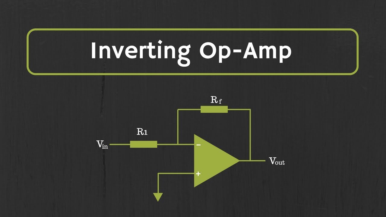
- 😀 The output of an inverting amplifier is given by the formula: V_o = - (R_f / R_1) * V_i.
- 😀 The non-inverting amplifier has an output given by: V_o = (1 + R_f / R_1) * V_i, always providing a gain greater than one.
- 😀 A voltage buffer outputs the same voltage as its input (V_o = V_i) and is used for impedance matching.
- 😀 In both amplifier configurations, the feedback resistor (R_f) is in the numerator, highlighting the effect of negative feedback.
- 😀 The output impedance of ideal op-amps is considered zero, allowing them to supply necessary output voltages without resistance.
- 😀 The input impedance of the inverting amplifier equals R_1, while the non-inverting amplifier and voltage buffer have infinite input impedance.
- 😀 Common resistor values for R_1 in inverting amplifiers typically range from 10k to 100k ohms to balance noise and current handling.
- 😀 High resistance values can introduce noise, while very low values can lead to excessive current, potentially damaging real op-amps.
Please replace the link and try again.
Outlines

This section is available to paid users only. Please upgrade to access this part.
Upgrade NowMindmap

This section is available to paid users only. Please upgrade to access this part.
Upgrade NowKeywords

This section is available to paid users only. Please upgrade to access this part.
Upgrade NowHighlights

This section is available to paid users only. Please upgrade to access this part.
Upgrade NowTranscripts

This section is available to paid users only. Please upgrade to access this part.
Upgrade NowBrowse More Related Video

Op Amp Voltage Subtractors and Superpositional Thinking (ECE Design Fundamentals, GA Tech course)
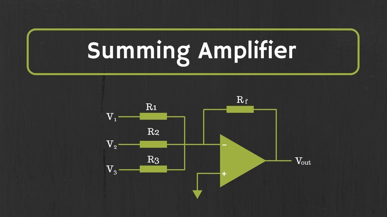
Op-Amp: Summing Amplifier (Inverting and Non-Inverting Summing Amplifiers)

Rangkaian Komparator OP AMP

Operational Amplifiers - Inverting & Non Inverting Op-Amps

Membaca dan Mengukur dengan Osiloskop
Operational Amplifier: Inverting Op Amp and The Concept of Virtual Ground in Op Amp
5.0 / 5 (0 votes)