Metodología ANSI/AGMA para diseño de engranes rectos y helicoidales parte 1
Summary
TLDRThis video delves into the intricacies of gear design, focusing on the flexural and wear stresses that affect gear teeth. It covers how these forces can cause gear failures and explains the methodology used to design gears to withstand such stresses. The course also compares straight and helical gears, highlighting their differences in power transmission, axial forces, and material considerations. Emphasizing the importance of material hardness and surface treatments, it provides insight into how engineers optimize gear designs for durability and efficiency, including solutions for managing axial forces in helical gear systems.
Takeaways
- 😀 The course focuses on gear design, particularly on ensuring gears can withstand forces and stresses without failing.
- 😀 The design of gears aims to handle two main failure modes: flexion (bending) and wear (abrasion).
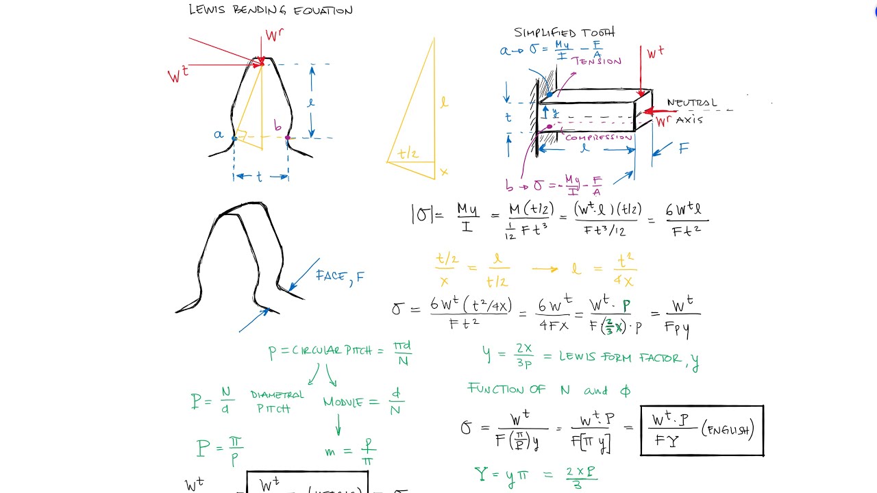
- 😀 Flexion occurs when the gear tooth bends under force, leading to stress concentration that may cause cracks and breakage.
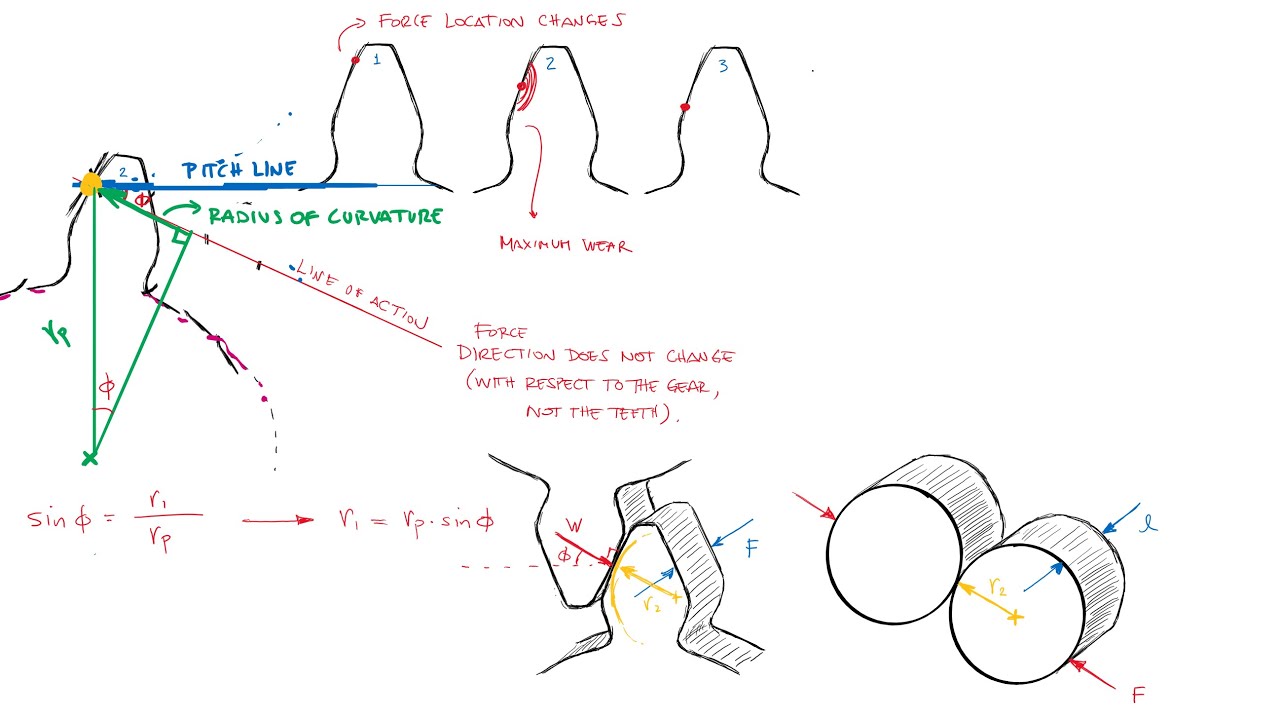
- 😀 Wear happens when gear teeth repeatedly engage, weakening the material due to constant friction, similar to hammering.
- 😀 The gear design methodology is based on a standard of 10 million (10^7) load cycles, though this can be adjusted based on specific needs.
- 😀 Material selection for gears is influenced by factors like hardness, carbon content, and surface treatment to resist wear and bending.
- 😀 Spur gears are simpler to manufacture but less efficient, as they generate more vibration and noise during operation.
- 😀 Helical gears transmit more power smoothly because of their angled teeth but generate axial forces that require specialized bearings.
- 😀 The axial force in helical gears results in the need for additional support systems, which can increase cost and complexity.
- 😀 A key difference between helical and spur gears is that helical gears offer greater efficiency and load distribution, but spur gears are simpler and cheaper to produce.
- 😀 The gear design methodology also considers the number of load cycles to ensure the gear can meet durability requirements and operational conditions.
Q & A
What are the two main factors that influence gear design?
-The two main factors that influence gear design are flexion and wear. Flexion occurs when a gear tooth is subjected to forces from the adjacent tooth, leading to stress and potential failure. Wear happens when the gear teeth repeatedly come into contact, causing surface degradation over time.
What is the primary goal when designing gears?
-The primary goal of gear design is to ensure the gear can support the required loads without failure due to flexion or wear. The gear must be designed to handle these forces while transmitting power efficiently.
What happens when flexion occurs in a gear?
-When flexion occurs, stress concentrates at the base of the gear tooth, which can lead to cracks and eventual tooth failure. This is a critical aspect of gear design to prevent the gear from breaking under load.
How does wear affect gears over time?
-Wear occurs when the teeth of the gears repeatedly come into contact, causing a 'hammering' effect. This weakens the surface of the teeth, leading to deterioration and eventual gear failure.
What is the typical cycle life for gears designed using the discussed methodology?
-The methodology discussed in the script is designed for a typical cycle life of 10^7 cycles. This cycle life is a standard assumption, unless adjustments are made based on specific design needs or material considerations.
How can the cycle life of gears be adjusted in the design process?
-The cycle life of gears can be adjusted by modifying factors such as material hardness and treatment, which affect wear and flexion resistance. If the cycle life is changed from the standard 10^7 cycles, different equations and factors are used in the design process.
What is the significance of material hardness in gear design?
-Material hardness plays a crucial role in both the wear and flexion resistance of gears. Harder materials generally have better resistance to wear and can handle higher flexion stresses, which contributes to the durability of the gear.
What is the difference between straight gears and helical gears?
-Straight gears have parallel teeth and are simpler to design, while helical gears have angled teeth that provide smoother operation and greater power transmission. However, helical gears generate axial forces that require special bearings to handle the load.
Why are helical gears preferred over straight gears in many applications?
-Helical gears are preferred because they offer higher power transmission, smoother operation, and less vibration. These advantages make them more efficient, especially in applications like automotive transmissions, despite being more expensive to produce.
What challenge arises from the axial forces generated by helical gears?
-The axial forces generated by helical gears require the use of bearings designed to support these axial loads. This adds complexity and cost to the gear design, as the bearings need to be able to handle the additional forces exerted by the helical teeth.
Outlines

This section is available to paid users only. Please upgrade to access this part.
Upgrade NowMindmap

This section is available to paid users only. Please upgrade to access this part.
Upgrade NowKeywords

This section is available to paid users only. Please upgrade to access this part.
Upgrade NowHighlights

This section is available to paid users only. Please upgrade to access this part.
Upgrade NowTranscripts

This section is available to paid users only. Please upgrade to access this part.
Upgrade NowBrowse More Related Video
LEWIS BENDING STRESS at the Teeth of a Gear in Just Over 12 Minutes!

solidworks tutorial - how to make spur gear . specially for beginers.
Gear PITTING - Surface Contact Stress Fatigue Failure in Just Over 10 Minutes!
Fixed Gear & Shock Absorption - Landing Gear - Airframes & Aircraft Systems #14

CARA MEMBUAT RODA GIGI DENGAN GAMPANG❕| BELAJAR AUTOCAD PART 3
Nose Gear - Landing Gear - Airframes & Aircraft Systems #16
5.0 / 5 (0 votes)