Understanding FM Receiver Basics : GATE Communications
Summary
TLDRThe video covers the fundamentals of an FM receiver, explaining its components and functionality compared to an AM receiver. It emphasizes the use of a superheterodyne receiver for both AM and FM, highlighting the differences in demodulation and additional blocks like amplitude limiters. Concepts such as pre-emphasis and de-emphasis are discussed to enhance audio quality by managing signal-to-noise ratios. The video also explains the fidelity of FM receivers, the selection of intermediate frequency (IF), and noise reduction mechanisms, providing an understanding of the signal processing in FM broadcast systems.
Takeaways
- 📡 The FM receiver operates in the frequency range of 88 MHz to 108 MHz, and it uses a superheterodyne receiver like AM, with the main difference being in the demodulation process and additional blocks.
- 📶 The receiving antenna is the first block, designed to capture signals across the full FM broadcasting range of 88 MHz to 108 MHz.
- 🎛️ Multi-stage RF amplifiers are used to amplify all possible signals without the issue of image frequencies, as the image frequency is kept outside the tuning range due to a carefully selected intermediate frequency (IF).
- 🔄 The mixer block, working with a local oscillator, converts frequencies using down-conversion (FL - FS = IF). The local oscillator frequency (FL) is always greater than the signal frequency (FS).
- 📈 The IF amplifier stage is crucial for signal selection, designed with a fixed IF value of 10.7 MHz and a bandwidth of 200 kHz, ensuring proper signal selection and tuning.
- 🔊 An amplitude limiter (double-ended clipper) is used to reduce noise by clipping amplitude variations, as FM signals do not carry information in the amplitude component.
- 📡 FM demodulation is done using a phase-locked loop (PLL), which is followed by an audio and power amplification process to enhance the signal for loudspeakers.
- ⚙️ Pre-emphasis at the transmitter and de-emphasis at the receiver are used to improve the signal-to-noise ratio, particularly for higher frequency components.
- 📊 Pre-emphasis artificially boosts higher frequency components at the transmitter to improve their signal-to-noise ratio before modulation, while de-emphasis reverses this process at the receiver after demodulation.
- 🎶 Fidelity is the ability of a radio receiver to reproduce all input frequencies accurately, and it is enhanced in FM receivers by using pre-emphasis and de-emphasis to manage the signal-to-noise ratio.
Q & A
What is the frequency range for FM broadcasting?
-The frequency range for FM broadcasting is from 88 MHz to 108 MHz.
What type of receiver is used in both AM and FM systems?
-Both AM and FM systems use a superheterodyne receiver.
What is the purpose of a multi-stage RF amplifier in an FM receiver?
-The multi-stage RF amplifier is used to amplify each received signal to ensure they are strong enough for further processing.
Why is there no issue with image frequencies in an FM receiver?
-Image frequencies are not an issue in FM receivers because the intermediate frequency (IF) value is selected in such a way that image frequencies fall outside the tuning range.
What is the typical intermediate frequency (IF) used in FM receivers?
-The typical intermediate frequency (IF) used in FM receivers is 10.7 MHz.
What is the role of an amplitude limiter in an FM receiver?
-An amplitude limiter removes amplitude variations caused by noise, as FM signals do not carry information in their amplitude.
What is the significance of pre-emphasis and de-emphasis in FM transmission?
-Pre-emphasis boosts high-frequency components before transmission to improve the signal-to-noise ratio. De-emphasis reduces these boosted frequencies at the receiver to restore the original signal.
What is the purpose of the phase-locked loop (PLL) in FM demodulation?
-The phase-locked loop (PLL) in FM demodulation is used to lock onto the frequency of the incoming FM signal and demodulate it to retrieve the original audio signal.
What is the fidelity of a radio receiver?
-Fidelity is the capability of a radio receiver to reproduce all input frequencies accurately at the output.
Why is pre-emphasis needed in FM systems, but not in AM systems?
-Pre-emphasis is needed in FM systems to improve the signal-to-noise ratio for higher frequencies, as noise power increases with frequency. In AM systems, the audio signal range is limited to lower frequencies, making pre-emphasis unnecessary.
Outlines

This section is available to paid users only. Please upgrade to access this part.
Upgrade NowMindmap

This section is available to paid users only. Please upgrade to access this part.
Upgrade NowKeywords

This section is available to paid users only. Please upgrade to access this part.
Upgrade NowHighlights

This section is available to paid users only. Please upgrade to access this part.
Upgrade NowTranscripts

This section is available to paid users only. Please upgrade to access this part.
Upgrade Now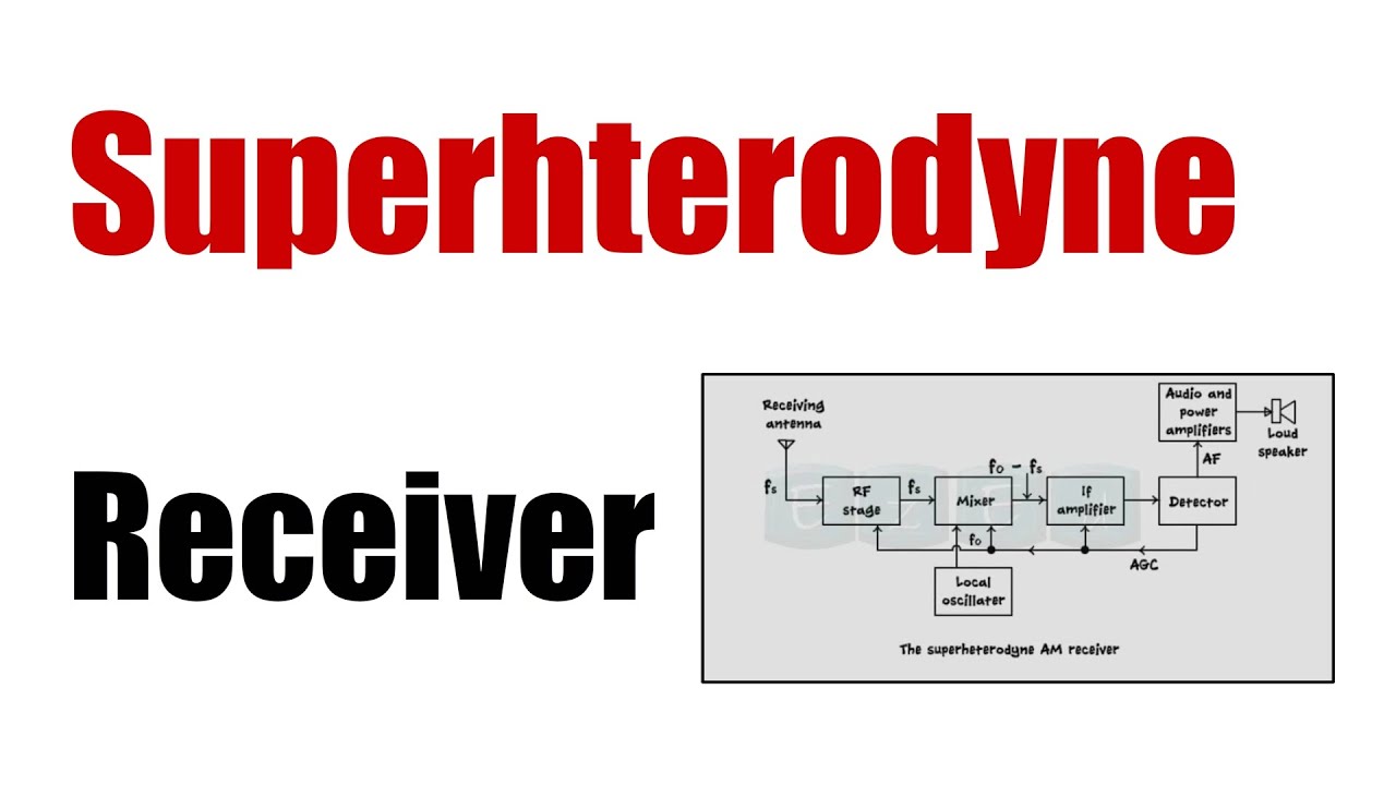


5.0 / 5 (0 votes)