GCSE Physics - Intro to circuits #14
Summary
TLDRThis video introduces the basics of electrical circuits, covering key components like cells, batteries, wires, and switches. It explains important concepts such as current (the flow of electrons), potential difference (voltage, driving the flow), and resistance (opposition to flow). The video highlights the direction of current, discussing conventional current flow (from positive to negative) versus actual electron flow (from negative to positive). Basic circuit symbols are introduced, helping viewers understand how to represent circuits in diagrams. The video concludes with a focus on key terms and their relevance for exams.
Takeaways
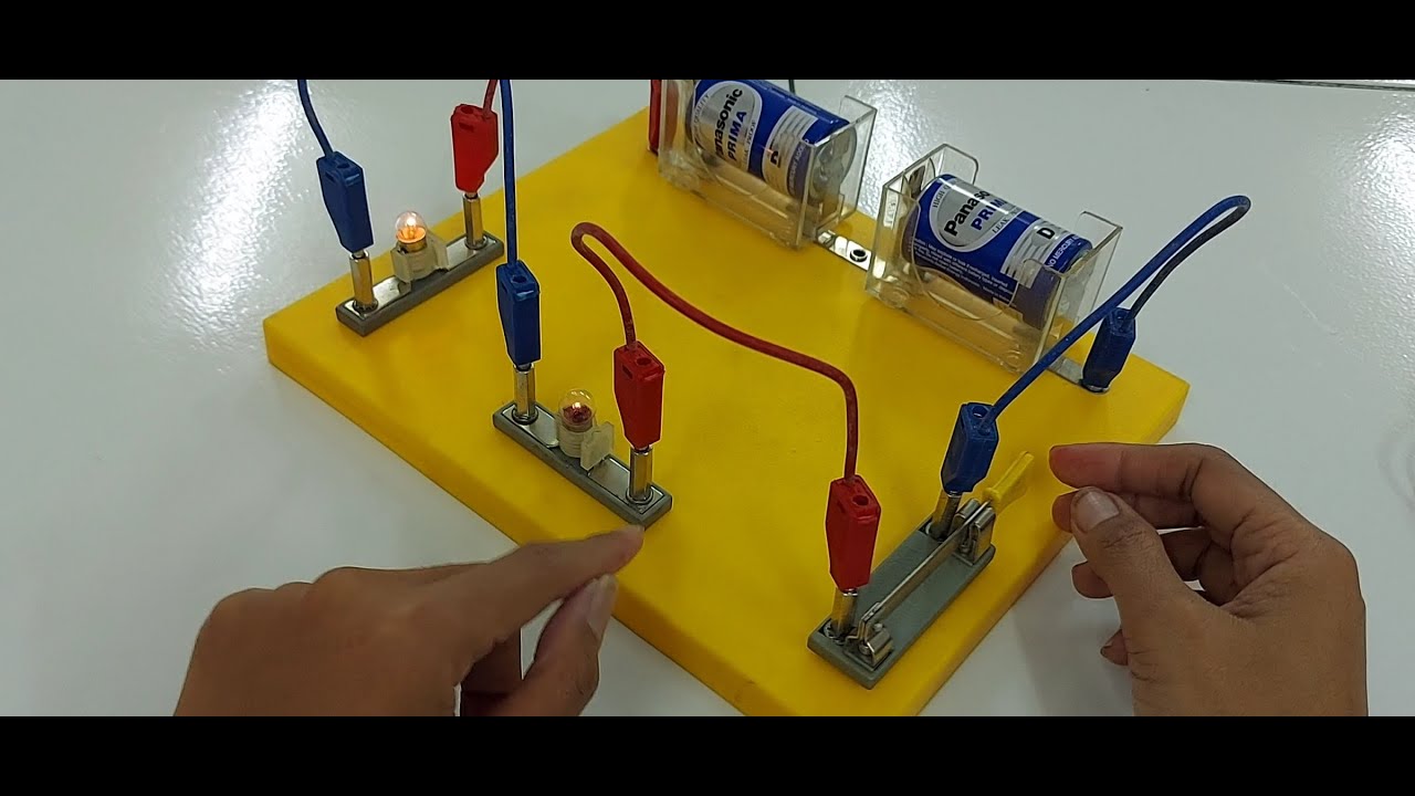
- 🔋 An electrical circuit is a closed loop that includes a power source like a cell and a pathway for electrons to flow, such as a wire.
- 📐 Circuits are represented by diagrams using specific symbols for various components.
- 🔋 A cell is a simple power source, while a battery consists of two or more cells connected together.
- 💡 A filament lamp symbol represents a small light bulb that lights up when connected to a power source.
- 🔌 A switch can either allow current to flow through the circuit when closed or stop the current when open.
- ⚡️ Current (I) represents the flow of electrons and is measured in amperes (A), similar to the flow of water in a pipe.
- 🔋 Potential difference (V), also called voltage, is the force that drives the flow of electrons, and is measured in volts.
- ⚙️ Resistance (R) opposes the flow of electrons in the circuit and is measured in ohms (Ω).
- 🔄 Electrons flow from the negative terminal to the positive terminal of a cell, but conventional current flows from positive to negative.
- 📜 Conventional current direction was decided before discovering electron flow, and this convention is still used in circuit diagrams.
Q & A
What is an electrical circuit?
-An electrical circuit is a closed loop that contains a power source, such as a cell, and something for the electrons to flow through, like a wire.
What is the purpose of a circuit diagram?
-A circuit diagram represents an electrical circuit using symbols to show the components and their connections. It helps in drawing and understanding circuits more easily.
What are the main components introduced in the video?
-The main components introduced are a cell (or battery), a filament lamp (light bulb), and a switch.
What is the symbol for a cell or battery in a circuit diagram?
-The symbol for a cell is a simple version of a battery. A battery, which is made up of two or more cells, is represented by two cell symbols put together.
What happens when a switch is added to a circuit?
-A switch can either allow current to flow when it is closed, or it can stop the flow of current by opening the circuit, which would turn off components like a light bulb.
What is electrical current and how is it measured?
-Electrical current is the flow of electrons around the circuit. It is measured in amperes, commonly called amps, and denoted by the letter 'A'.
What is potential difference (voltage) and its role in a circuit?
-Potential difference, also known as voltage, is the force driving the flow of electrons in a circuit. It is provided by the cell or battery and is measured in volts, denoted by 'V'.
What is resistance and how does it affect a circuit?
-Resistance is anything that opposes the flow of electrons in a circuit, similar to a blockage in a pipe. It is measured in ohms and denoted by 'R'.
Which direction do electrons flow in a circuit?
-Electrons flow from the negative terminal to the positive terminal of the cell, because they are negatively charged.
What is conventional current and how does it differ from actual electron flow?
-Conventional current is the flow of current from the positive terminal to the negative terminal, which was the original assumption before electrons were discovered. This is opposite to the actual electron flow, which goes from negative to positive.
Outlines

This section is available to paid users only. Please upgrade to access this part.
Upgrade NowMindmap

This section is available to paid users only. Please upgrade to access this part.
Upgrade NowKeywords

This section is available to paid users only. Please upgrade to access this part.
Upgrade NowHighlights

This section is available to paid users only. Please upgrade to access this part.
Upgrade NowTranscripts

This section is available to paid users only. Please upgrade to access this part.
Upgrade NowBrowse More Related Video

DASAR-DASAR RANGKAIAN KELISTRIKAN OTOMOTIF || BELAJAR OTOMOTIF
Video Pembelajaran IPA Rangkaian Listrik Seri dan Paralel menggunakan KIT

Series & Parallel Circuits EXPLAINED with Kirchhoff's Circuit Laws // HSC Physics

BASIC ELECTRONIC COMPONENTS

Tutorial Cara Membuat Rangkaian Listrik Seri-Pararel-Campuran Oleh Naura AdhwaSyakeera 6D
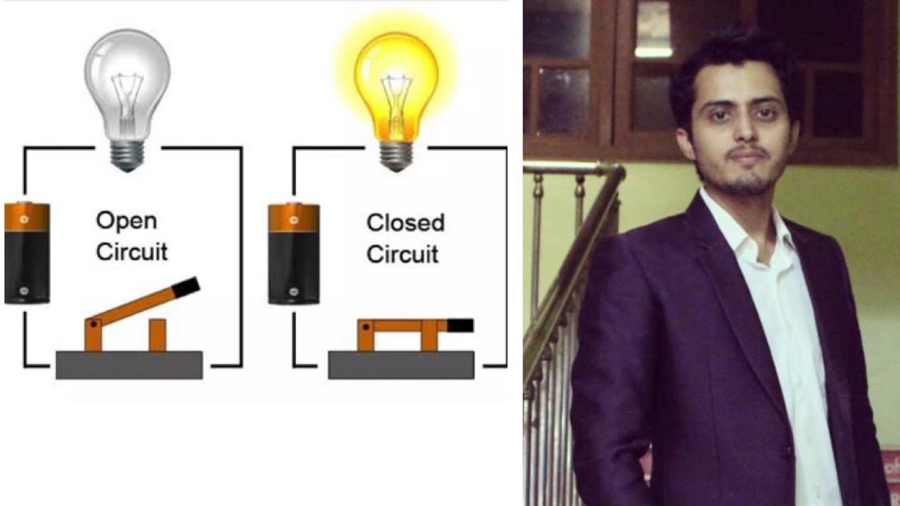
Open circuit | closed circuit | Short circuit | Easiest way to understand
5.0 / 5 (0 votes)