AUTOMATIC POWER FACTOR CORRECTION USING ARDUINO // Engineering / electrical / electronic / diploma
Summary
TLDRThis video demonstrates an automatic power factor correction system using Arduino. It includes a step-down transformer, voltage regulator, Arduino board, LCD display, capacitor bank, relays, and a CT for an inductive load. The system can operate in lagging and composting modes, automatically correcting power factor by adjusting the capacitor bank via relays. A manual mode is also provided for demonstration and study purposes, allowing users to manually adjust the power factor by controlling the capacitors.
Takeaways
- 🔌 **Hardware Components**: The system includes a Step Down Transformer, Voltage Regulator, Arduino Board, LCD Display, Capacitor Bank, Relays, Relay Driver ICs, and an Inductive Load CT.
- 📊 **Initial Power Factor**: The power factor starts at 0.56 with an inductive load, indicating a lagging power factor.
- ⏱️ **Current Lag**: The 'I lag' is initially 3.2 msec due to the inductive load.
- 💡 **Automatic Correction**: Arduino automatically turns on two relays to correct the power factor.
- 🔄 **Power Factor Unity**: When the inductive load is off, the 'I lag' decreases near to zero, achieving a power factor of unity.
- 🔁 **Reactive Power**: When the inductive load is back, the 'I lag' returns to 3.2 msec, and the power factor drops to 0.53.
- 📈 **Manual Mode**: A manual mode is available for demonstration and study purposes, allowing for manual control of power factor correction.
- 🎛️ **Mode Switching**: The system can switch between lagging and composting modes, affecting how the current waveform is processed by the Arduino.
- 🔋 **Capacitor Bank Adjustment**: By pressing buttons, capacitors can be added or removed from the circuit to adjust the 'I lag' and improve the power factor.
- 🔄 **Dynamic Correction**: The project works in both manual and auto modes, allowing for dynamic correction of the power factor.
- 📚 **Educational Tool**: The kit serves as an educational tool to understand automatic power factor correction concepts.
Q & A
What is the purpose of the project described in the script?
-The purpose of the project is to demonstrate automatic power factor correction using an Arduino.
What are the main components required for this project?
-The main components include a Step Down Transformer, Voltage Regulator circuit, Arduino Board, LCD Display, Capacitor Bank, Relays for switching the capacitor bank, Relay Driver ICs, and an Inductive Load CT.
What is the initial power factor with the inductive load present?
-The initial power factor with the inductive load present is 0.56.
How does the Arduino correct the power factor?
-The Arduino corrects the power factor by automatically turning on two relays to switch capacitors in the bank, which adjusts the power factor.
What happens to the 'I lag' when the inductive load is turned off?
-When the inductive load is turned off, 'I lag' decreases and approaches zero, resulting in a power factor of unity.
What is the role of the capacitor bank in this project?
-The capacitor bank is used to provide reactive power compensation to correct the power factor by balancing the inductive reactive power.
What is the significance of the 'lagging mode' mentioned in the script?
-In the 'lagging mode', the current waveform is derived solely from the inductive load, which causes the power factor to lag.
How does the 'composting mode' differ from the 'lagging mode'?
-In the 'composting mode', the waveform is developed by both the capacitive and inductive loads, which helps in achieving a more balanced power factor.
What is the manual mode for in this project?
-The manual mode allows for the adjustment of the power factor by manually pressing buttons to add or remove capacitors from the circuit.
What happens when one button is pressed in manual mode?
-Pressing one button in manual mode results in an improved power factor of 0.33 due to the addition of one capacitor, reducing 'I lag' to 1.56 msec.
What is the effect of adding another capacitor while in manual mode?
-Adding another capacitor in manual mode causes 'I' to lead by 1.9 msec, which decreases the improved power factor.
How does the LCD display contribute to the project?
-The LCD display shows the current status of the power factor and 'I lag', providing real-time feedback on the system's performance.
Outlines

This section is available to paid users only. Please upgrade to access this part.
Upgrade NowMindmap

This section is available to paid users only. Please upgrade to access this part.
Upgrade NowKeywords

This section is available to paid users only. Please upgrade to access this part.
Upgrade NowHighlights

This section is available to paid users only. Please upgrade to access this part.
Upgrade NowTranscripts

This section is available to paid users only. Please upgrade to access this part.
Upgrade NowBrowse More Related Video

Project Membuat Palang pintu otomatis Jalan tol
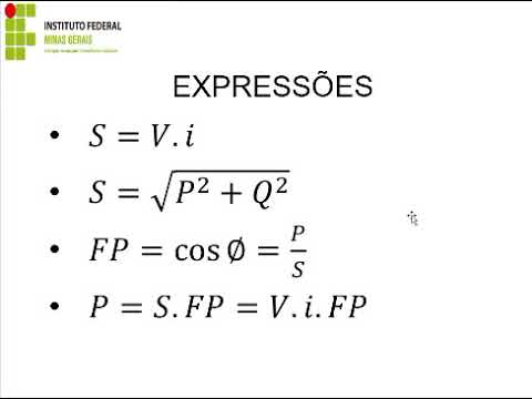
Fator de Potência / Correção do FP
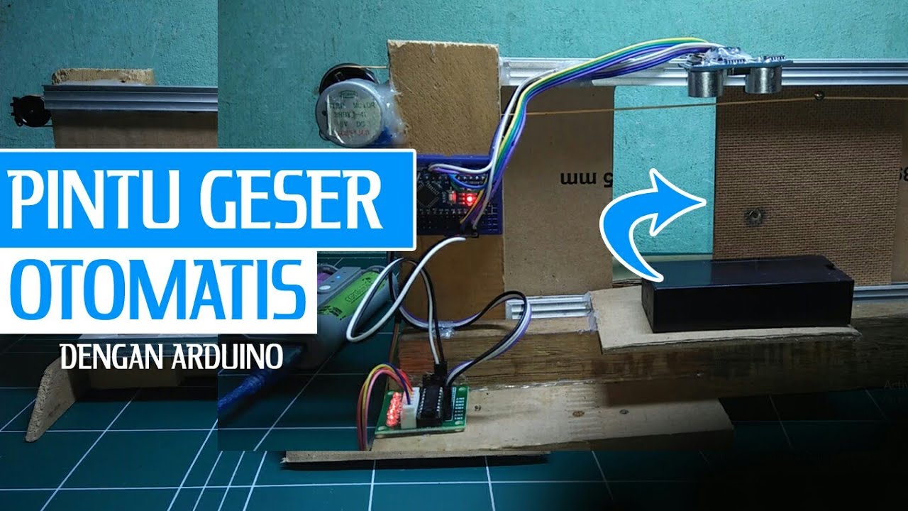
Membuat Pintu geser otomatis | automatic sliding door
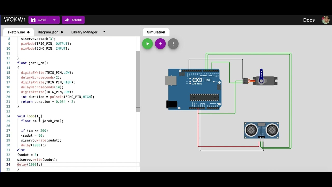
Simulasi kontrol gerakan servo dengan sensor ultrasonik | mikrokontroler arduino di wokwi.com

DIY hand sanitizer automatic dispenser infrared & servo
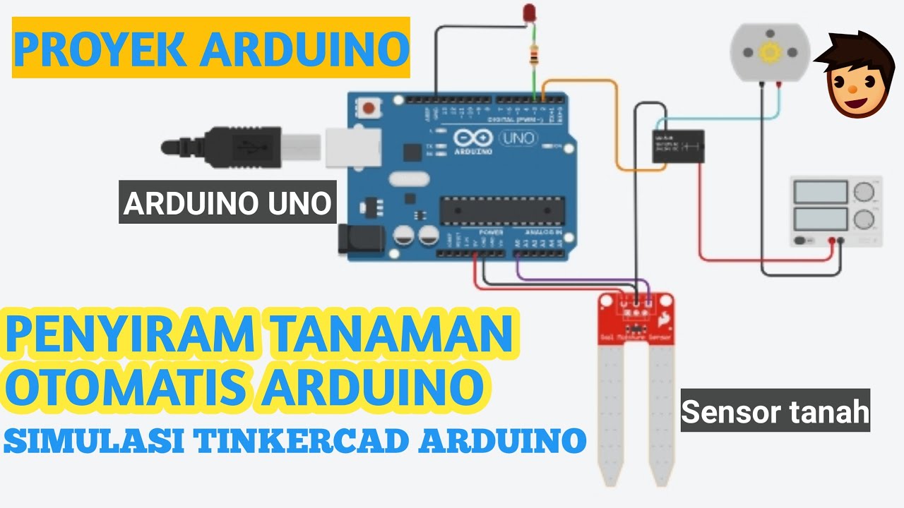
PROYEK ARDUINO PENYIRAM TANAMAN OTOMATIS DENGAN SENSOR KELEMBABAN TANAH SIMULASI TINKERCAD ARDUINO
5.0 / 5 (0 votes)