L1VSetup

ISstemEd
5 Jun 202007:29

Summary

TLDRThis instructional script guides viewers through assembling a basic electrical circuit using components like resistors, wires, and a breadboard. It emphasizes the importance of series connections and safely operating a power supply to provide voltage and current. The tutorial demonstrates how to connect an ammeter to measure current and concludes with a cautionary note on the proper shutdown procedure to prevent damage to the circuit.

Takeaways

  • πŸ”Œ To make electrical connections in series, you can hold two wires together or solder them.
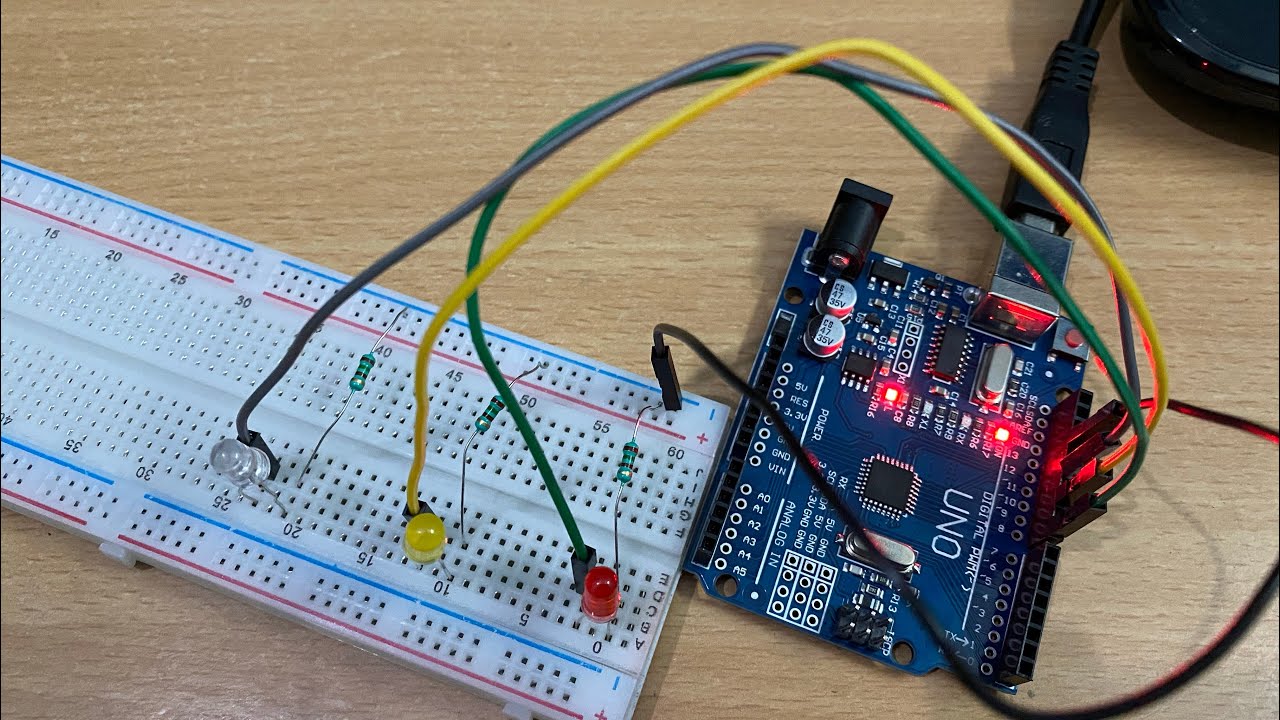
  • πŸ“Œ A breadboard is a useful tool for creating connections without soldering; it allows components to be easily connected along its rows.
  • πŸ”© When setting up a circuit, ensure that the power supply's current and voltage are turned down before making connections.
  • πŸ”΅ The color-coding of wires is important; typically, red or black wires are used for the positive and negative connections, respectively.
  • πŸ”‹ The power supply should be connected to the circuit with the positive lead plugged into the red (or positive) side and the ground into the blue (or negative) side.
  • ⚑ It's crucial to attach the resistor to the circuit by connecting one side to the power supply's positive terminal and the other side to complete the circuit through the breadboard.
  • πŸ“ˆ An ammeter is used to measure the current flowing through the circuit, and it should be connected in series with the resistor.
  • πŸ”„ Completing the circuit ensures that the current flows from the power supply, through the resistor, the ammeter, and back to the ground.
  • πŸ”’ Safety is paramount when working with electrical circuits; always turn the voltage and current down and power off before making or breaking connections.
  • πŸ“Š For experiments, gradually increase the voltage from the power supply while recording the corresponding current readings at each step, up to a maximum of 10 volts.

Q & A

  • What is the purpose of connecting components in series?

    -Connecting components in series ensures that the current flows through each component in the circuit in the same path, allowing for the control and measurement of current and voltage across each component.

  • How do you make a connection between a resistor and a wire?

    -You can make a connection by holding the lead of the resistor and the wire together or by soldering them. Alternatively, you can use a breadboard to easily plug the wire into the resistor's lead.

  • What is the function of a breadboard in a circuit?

    -A breadboard allows for easy and temporary connections between components without soldering. It has rows of holes that connect internally, enabling the user to build and modify circuits quickly.

  • How are the rows on a breadboard typically connected?

    -On a breadboard, all the holes in a single row are connected internally. However, rows are not connected to each other unless they are in the same column or row.

  • Why is it important to turn the current and voltage down before connecting a circuit to a power supply?

    -Turning the current and voltage down before connecting a circuit ensures safety by preventing any sudden high power flow that could damage the components or create a hazard.

  • What is the role of an alligator clip in a circuit setup?

    -An alligator clip is used to easily attach and detach wires from a power supply or other components. It provides a secure connection and is often used for making temporary connections in a circuit.

  • How do you connect a resistor to a power supply using a breadboard?

    -You connect a resistor to a power supply by plugging one end of the resistor into the breadboard and then using a wire connected to the power supply to plug into the same row on the breadboard, completing the circuit.

  • What is the purpose of an ammeter in a circuit?

    -An ammeter is used to measure the current flowing through a circuit. It is connected in series with the components to monitor the amount of current or amps passing through.

  • Why is it recommended to turn off the power supply and reduce the current and voltage to zero after taking measurements?

    -Turning off the power supply and reducing the current and voltage to zero after taking measurements is a safety precaution to prevent overheating or damage to the components and to ensure that the next user does not encounter a potentially dangerous high voltage or current when they start their experiment.

  • What is the significance of not exceeding 10 volts in the described circuit experiment?

    -Not exceeding 10 volts in the experiment is to prevent overdriving the circuit, which could lead to component damage or inaccurate measurements. It ensures that the circuit operates within safe and expected parameters.

Outlines

00:00

πŸ”Œ Connecting Components in a Series Circuit

This paragraph explains the process of connecting different electronic components, such as resistors and wires, in a series circuit. It highlights the use of a breadboard to simplify connections by allowing components to be plugged into it, making it easier to create a circuit without soldering. The paragraph also describes how to connect a resistor to a power supply using alligator clips and wires, ensuring that the circuit is completed properly. It emphasizes the importance of setting the power supply to zero before starting and adjusting the voltage and current as needed during the experiment.

05:00

πŸ”‹ Safely Operating a Power Supply for Circuit Testing

The second paragraph focuses on the safe operation of a power supply when testing a circuit. It instructs to turn the current and voltage down to zero before turning on the power supply and to take measurements at various voltage levels, ensuring not to exceed 10 volts to prevent damaging the circuit. The paragraph also stresses the importance of safety procedures, such as turning off the power supply and resetting the current and voltage to zero after use. This is to prevent any accidents or damage to the equipment when it is not in use or when another person uses it next.

Mindmap

Keywords

πŸ’‘Series Connection

A series connection refers to a configuration where components in an electrical circuit are connected end-to-end in a single path so that the current flows through each component sequentially. In the video, the concept is central to building the circuit as it explains how to connect a resistor to a wire in series, ensuring that the electrical current passes through each component in turn, as illustrated by connecting a wire to another wire or to a resistor.

πŸ’‘Resistor

A resistor is a passive electronic component that opposes the flow of electric current in a circuit. Its primary function is to limit or regulate the amount of current. In the script, a resistor is used as a part of the circuit, and the process of connecting it to other components via wires or a breadboard is discussed, showcasing its role in controlling the current flow within the circuit.

πŸ’‘Breadboard

A breadboard is a versatile tool used in electronics for prototyping and testing circuits without soldering. It allows users to easily connect and disconnect components using spring clips. The video script mentions using a breadboard to make connections along a line, which simplifies the process of wiring components together in a circuit, such as connecting a wire to a resistor.

πŸ’‘Alligator Clip

An alligator clip is a type of spring-loaded electrical connector named for its resemblance to an alligator's jaw. It is used to make temporary connections in a circuit. In the context of the video, alligator clips are used to attach wires to a power supply, facilitating the flow of current from the power source to the components in the circuit.

πŸ’‘Power Supply

A power supply provides the necessary electrical power to a circuit. It converts mains AC voltage to the lower voltages required by electronic devices. The script describes setting up a power supply with specific current and voltage settings, emphasizing the importance of starting with the power off and adjusting the settings to ensure safe operation of the circuit.

πŸ’‘Voltage

Voltage, also known as electric potential difference, is the force that pushes electric charge through a conductor. In the video, voltage is adjusted on the power supply to provide the necessary potential difference for current to flow through the circuit, with caution advised not to exceed safe levels to prevent damage to the components.

πŸ’‘Current

Electric current is the flow of electric charge through a conductor. The video script instructs on how to set the power supply to adjust the current flowing through the circuit, which is crucial for testing and measurement purposes. The current is measured in amperes (amps), and the script mentions using an ammeter to read the current.

πŸ’‘Ammeter

An ammeter is an instrument used to measure the electric current flowing in a circuit. In the script, an ammeter is connected in series with a resistor to measure the current passing through it. The setup illustrates how to read the amount of current, which is a key parameter in understanding the circuit's behavior.

πŸ’‘Circuit

A circuit is a closed loop through which electric current flows. The video script provides a step-by-step guide on creating a simple series circuit, which is a fundamental concept in electronics. The circuit completion is essential for demonstrating the relationship between voltage, current, and resistance in an electrical system.

πŸ’‘Safety Procedures

Safety procedures in electronics involve a set of practices to prevent injury or damage to equipment. The script emphasizes the importance of turning the voltage and current down before connecting or disconnecting components, and turning off the power supply when not in use. These procedures are crucial for protecting both the user and the electronic components.

πŸ’‘Data Point Measurements

Data point measurements refer to the process of collecting specific values or readings from a circuit under controlled conditions. The video script mentions taking data point measurements at different voltage levels to understand how the current changes, which is a fundamental aspect of experimental electronics and helps in analyzing the circuit's performance.

Highlights

Explanation of how to connect components in series using wires and resistors.

Demonstration of making electrical connections by holding or soldering wires together.

Introduction to using a breadboard for circuit connections and its ease of use.

Description of how a breadboard connects components along its lines.

Tutorial on hooking a wire to a resistor using a breadboard.

Guidance on completing a circuit by connecting a resistor to a power supply.

Instructions on setting up a power supply with alligator clips for a circuit.

Emphasis on safety by turning down the current and voltage before connecting the circuit.

Step-by-step guide to attaching wires to a resistor from the power supply.

Use of an ammeter to read the current in a circuit.

Detailed process of completing a series circuit with a resistor and an ammeter.

Procedure for safely using a power supply by turning off and resetting current and voltage.

Advice on not exceeding 10 volts to prevent damaging the circuit.

Importance of turning off the power supply after use to ensure safety.

Recommendation to follow safety procedures when working with electrical circuits.

Final reminder to turn off the power supply completely after use.

Transcripts

play00:00

so you're gonna have to hook different

play00:03

components together and make connections

play00:05

between components and wires so again to

play00:08

make the connection this is gonna be in

play00:11

series so if you've got a resistor looks

play00:14

like this you got a wire and you got

play00:17

this lead right here and let's say you

play00:19

wanted to connect it to another wire so

play00:22

again what you'd have to do is you'd

play00:23

have to hold these connections like that

play00:28

to make that connection or you'd have to

play00:29

solder it but the way around that is you

play00:31

can use a breadboard so with a

play00:34

breadboard

play00:36

everything along this line right here is

play00:39

connected it would be making that

play00:41

connection of just holding those two

play00:42

wires together as well as this these are

play00:46

all connected but this one and this one

play00:47

is not connected now along this side

play00:49

these are all connected but it's not

play00:52

connected from there to there and these

play00:54

are all connected so again if I wanted

play00:56

to hook a wire to a resistor I could

play01:00

plug it into here and I could plug it

play01:03

into here to hold the wire and then if I

play01:09

wanted to connect the wire do that when

play01:13

I would plug it into the space that's

play01:15

along that particular line so I could

play01:18

take a wire and I plugged it into that

play01:24

line and you can see that so again it

play01:29

plugged in here the resistor and the

play01:32

wires plugged in here so again we've

play01:34

completed that circuit it's like

play01:35

attaching those two wires together all

play01:39

right so now you're going to complete

play01:41

the lab the first circuit that you're

play01:45

gonna want to build so again we've got

play01:46

our power supply right here and you'll

play01:49

want to hook a wire with an alligator

play01:52

clip and attach a wire such as this the

play01:55

to the ground and do the same thing for

play01:59

the power and the way we're going to put

play02:06

power into it as we've got this current

play02:07

and the voltage and you're going to want

play02:10

to make sure they're all turned all the

play02:12

way down so

play02:13

turning it counterclockwise alright so

play02:17

then you're gonna want to create the

play02:18

circuit so what we've got here is we've

play02:21

got our board so what you'll do is

play02:22

you'll take the positive and plug it

play02:25

into that positive along that whole

play02:28

strip and then take the negative and

play02:31

plug it into the blue so I'll plug the

play02:34

red or plug the positive into the red

play02:37

side and plug the ground into the blue

play02:42

side and what you can do is it'll look

play02:45

like this so now again I've got the

play02:48

positive here and I've got the ground

play02:51

plugged into here and that's completing

play02:54

it from the power supply okay the next

play03:00

thing that you're gonna want to do is

play03:01

you're gonna want to attach from the

play03:08

positive side of the voltage where

play03:10

you're going to be getting the bolt and

play03:12

you're going to want to attach it to the

play03:14

one side of this resistor so what we do

play03:16

is we take a wire that's also in

play03:20

connected to that power supply and

play03:22

attach it to the one side of the

play03:25

resistor that we have right here so we

play03:28

can see then we have the wire from the

play03:32

positive side the purple wire hooked

play03:34

into the one side of the resistor okay

play03:38

so now what we've got is our ammeter

play03:40

that's going to read the amount of

play03:42

current or the amps and what we've got

play03:43

is we've got the red side and the ground

play03:46

side right here so again we want to

play03:49

attach wires so I attached the blue wire

play03:53

to the red and I attach the white wire

play03:59

to the black and we want to hook those

play04:00

in to complete the circuit and again we

play04:02

want it to be in series so I take the

play04:08

blue wire that's hooked to the red wire

play04:10

and I plug that into the breadboard

play04:14

where it has to flow through the

play04:17

resistor through this wire and then I

play04:22

want to end the circuit so again this

play04:24

has got to end

play04:25

what I've got here and I'm gonna want to

play04:28

plug that into the ground side so where

play04:33

I hook the power supply black wire into

play04:38

this blue line so I can plug it in

play04:40

anywhere along there so essentially what

play04:45

I've got going in is if I look at this I

play04:49

got the power going into here and going

play04:53

from here to the resistor through the

play04:56

resistor through the amp meter through

play05:00

those connections and then back to the

play05:04

ground which again goes back to the

play05:06

power supply okay so now to use the

play05:11

power supply again you want it before

play05:15

you turn it on turn the current and the

play05:17

voltage all the way down and then turn

play05:19

on the power and you can see right here

play05:21

we've got our volts at five I mean our

play05:24

current at zero sir bolt is at point

play05:27

five okay

play05:29

so the next thing that you want to do is

play05:30

you want to turn the current all the way

play05:31

up but leaving the voltage down so again

play05:35

you're going to now turn the voltage up

play05:39

to increase the voltage so again follow

play05:42

what it says in the to take your data

play05:46

point measurements and I'll show you how

play05:47

to use that on the on the the next video

play05:50

how to actually get the current reading

play05:54

but again so what you're gonna want to

play05:55

do is again turn it up to two volts and

play05:59

you can adjust it again you'll take a

play06:02

reading and then you can turn it up to

play06:05

five volts and if you can't get it

play06:09

exactly five just put five point one and

play06:12

record that and then 7.5 volts

play06:21

or whatever you can get close to that

play06:23

and then ten volts so we don't want to

play06:26

go any greater than 10 volts so we don't

play06:30

want to be driving our circuit with too

play06:32

much power so that's what you'll do for

play06:40

your experiment and again it's going

play06:41

through the circuit okay after you're

play06:46

taking your data you want to make sure

play06:48

you turn the voltage all the way down

play06:51

the current all the way down and then

play06:53

turn the power off you don't want to

play06:55

leave your power supply on extended

play06:57

times things heat up things could burn

play07:00

out so again you want to make sure

play07:03

you're always using safety safety

play07:09

procedures and that's basically if

play07:11

you're not using the power supply turn

play07:12

it all the way down turn it off because

play07:15

the next person that hooks it back up

play07:17

you don't want to have the full voltage

play07:19

on or the full current so again just

play07:21

good process to go through turn the

play07:23

current down turn the voltage down turn

play07:25

the power power supply completely off

Rate This
β˜…
β˜…
β˜…
β˜…
β˜…

5.0 / 5 (0 votes)

Related Tags
Circuit BuildingResistorsWiringBreadboardsElectrical SafetyDIY ElectronicsVoltage ControlCurrent MeasurementLab ExperimentsEducational Tutorial