RSLogix 5000 Analog Input Programming | Wiring Scaling Tutorial for PLC Analog Input Signal Example
Summary
TLDRThis tutorial focuses on configuring and wiring a 1769-IF8 analog input card for a 0 to 5 volts signal on a 1769 I/O chassis. The presenter guides viewers through the process of setting up the card in Studio 5000, selecting the appropriate input range, and troubleshooting potential issues. They also demonstrate how to convert raw data into engineering units for better understanding and accuracy, ensuring the analog signal is correctly interpreted within the PLC system.
Takeaways
- 😀 The tutorial focuses on setting up an analog input card (1769-IF8) for a voltage signal ranging from 0 to 5 volts on a 1769-IF/8 card.
- 🔌 It covers the process of wiring the card, configuring it in Studio 5000, and understanding how to interface it with the L/24 ER processor.
- 💻 The video provides a step-by-step guide on how to add and configure the analog input module in Studio 5000 software.
- 🔍 It demonstrates how to use RSLinx Classic Lite to identify the module and check its properties, including the catalog number and revision number.
- 🛠️ The tutorial explains the importance of selecting the correct input range for the analog card to ensure accurate readings.
- 📊 It discusses the data format options available in the analog card configuration, including raw/proportional and engineering units.
- 🔩 The video includes a practical demonstration of how to wire the analog input card, emphasizing the differential voltage type with a common and positive signal.
- 📈 It shows how to troubleshoot and calibrate the analog input to ensure stable and accurate readings, including adjusting the filter settings.
- 📝 The presenter uses an HMI screen to generate test voltages for the analog input card, providing a hands-on example of how to verify the setup.
- 🔧 The tutorial concludes with a discussion on converting raw data into engineering units using the compute instruction in Studio 5000 for better understanding and usability of the data in the field.
Q & A
What is the main focus of the tutorial?
-The main focus of the tutorial is to demonstrate how to extract a voltage signal ranging from 0 to 5 volts into a 1769-IF8 card using an Allen-Bradley PLC.
What is the purpose of the extension IO in the context of the tutorial?
-The extension IO is used to communicate with modules that are on the extension bus of the L/24 ER processor.
How does one identify the correct module to configure in Studio 5000?
-To identify the correct module in Studio 5000, one can refer to the hardware label on the side of the module or use RSLinx Classic Lite to view the module's catalog number.
What is the significance of the Requested Packet Interval (RPI) in the configuration?
-The Requested Packet Interval (RPI) determines how frequently the card is polled for data. It can be adjusted based on the application's need for speed or accuracy.
Why is the input range selection important when configuring the analog card?
-The input range selection is important because it determines the accuracy of the readings. It should match the signal's voltage range to ensure precise data acquisition.
How does the tutorial suggest testing the analog card?
-The tutorial suggests using an HMI screen from AutomationDirect's Click PLC to generate and test different voltage signals to verify the analog card's functionality.
What is the purpose of the 'engineering units' setting in the analog card configuration?
-The 'engineering units' setting is used to convert raw proportional data into more meaningful units, such as voltage, making it easier to understand and use in applications.
Why might there be oscillation in the readings from the analog card?
-Oscillation in the readings could be due to incorrect wiring, high filter settings, or issues with the signal source. The tutorial suggests checking these aspects to resolve the issue.
How can the raw data from the analog card be converted into a more understandable voltage value?
-The tutorial demonstrates using a CPT (Compute) instruction in Studio 5000 to divide the raw data by 1000, converting it into a voltage value that corresponds to the input range of 0 to 5 volts.
What troubleshooting steps are suggested in the tutorial if the expected voltage is not being read?
-The tutorial suggests checking the wiring, adjusting the filter settings, and verifying the output from the signal source using a digital multimeter to ensure the correct voltage is being sent to the card.
Outlines

This section is available to paid users only. Please upgrade to access this part.
Upgrade NowMindmap

This section is available to paid users only. Please upgrade to access this part.
Upgrade NowKeywords

This section is available to paid users only. Please upgrade to access this part.
Upgrade NowHighlights

This section is available to paid users only. Please upgrade to access this part.
Upgrade NowTranscripts

This section is available to paid users only. Please upgrade to access this part.
Upgrade NowBrowse More Related Video
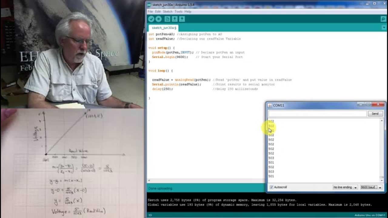
LESSON 10: Reading Analog Voltages with Arduino
Receive Analog Signals on a PowerFlex 525 & 755TS
MasterTool IEC XE - 6 - Uso de entradas analógicas

Input and Output Addressing in Siemens PLC - Tia Portal Tutorial

ESP32 tutorial A-06: Photo-resistor

Tutorial-5: Understanding Data Types in DataFlow Simulation
5.0 / 5 (0 votes)