A320 - Autoflight System (FCU - Flight Control Unit) PART 2
Summary
TLDRThis module provides an in-depth look at the functions and controls of the Flight Control Unit (FCU) used in aircraft operations. It covers key aspects like speed, lateral, and vertical control, as well as the use of autopilot and auto thrust. The video explains the difference between the selected and managed modes, how pilots interact with the FCU, and the various knobs and buttons that control flight parameters. It also touches on specific features like the localizer, approach, and expedite push buttons, which play crucial roles during flight.
Takeaways
- 😀 The Flight Control Unit (FCU) is crucial for controlling various flight parameters including speed, lateral, and vertical control, as well as autopilot and autothrust selection.
- 🔄 The FCU operates in two modes: Selected Mode, where the pilot actively selects flight parameters, and Managed Mode, where the aircraft is controlled by pre-set parameters in the Flight Management Guidance Computer (FMGC).
- 📍 In Selected Mode, pilots activate by pulling the desired knob, while in Managed Mode, they push the knobs to let the computer control the flight according to parameters input through the Multipurpose Control Display Unit (MCDU).
- ✈️ The Altitude window always shows the altitude set by the crew, and the knob can be used to set altitude in increments that can be adjusted from 100 feet to 1000 feet.
- 🔢 The Speed Mock Control area includes a window, a speed mark push button, and a speed mark selector knob, allowing the pilot to set and display the aircraft's speed.
- 🔄 The Heading Track Selector knob functions by pulling to display current heading, turning to change the heading track, and pushing to return to LNAV (Lateral Navigation).
- 🔄 The Heading Vertical Speed Track Flight Path Angle push button switches the reference from heading vertical speed to track flight path angle, adjusting the display and flight director accordingly.
- 🔼 The Vertical area is divided into altitude and vertical speed/flight path angle controls, with the altitude control allowing the aircraft to return to a pre-planned vertical profile or disregard it for manual input.
- ⏫⏬ The Vertical Speed Flight Path Angle knob controls level off commands when pushed, selects vertical speed or flight path angle when pulled, and changes these values when turned.
- 🔑 Additional FCU push buttons include Localizer for tracking a localizer, Approach for ILS acquisition, and Expedite for maximum rate climb or descent, showcasing the unit's comprehensive control over flight dynamics.
Q & A
What is the primary function of the Flight Control Unit (FCU)?
-The FCU is used for speed mock control, lateral control, vertical control, autopilot and/or auto thrust selection.
How many different operation modes can the FCU system be operated in?
-The FCU system can be operated in two different modes: Selected Mode and Managed Mode.
What does the pilot need to do in the Selected Mode?
-In the Selected Mode, the pilot must continuously select how he wants the airplane to fly, including speed, heading, and vertical speed.
How can the pilot activate the Selected Mode?
-To activate the Selected Mode, the pilot pulls the desired knob outward.
What happens in the Managed Mode in terms of airplane control?
-In the Managed Mode, the computers control the airplane according to parameters previously input into the FMGC through the MCDU.
Why are the speed and heading windows filled with dashes in the Managed Mode?
-The windows are filled with dashes because the FMGC is controlling speed and lateral navigation, and the pilot is not manually selecting these parameters.
What is the purpose of the speed mark selector knob in the speed mock control area?
-The speed mark selector knob controls several functions, including displaying the current aircraft speed and setting a speed in the window.
How does the heading track selector knob function?
-The heading track selector knob can be pulled to display the present aircraft heading, turned to change the heading track, or pushed to allow the aircraft to return to LNAV.
What is the use of the heading vertical speed track flight path angle push button?
-The push button is used to change the reference from heading vertical speed to track flight path angle.
How does the altitude window function in the vertical area?
-The altitude window always shows the altitude set by the crew and can be changed by turning, pushing, or pulling the altitude selector knob.
What is the purpose of the metric altitude push button?
-The metric altitude push button is used to display the selected altitude in meters on the permanent data section of the ECAM system display.
What does the Localizer push button do?
-The Localizer push button is used to acquire and track a localizer, with green lights indicating when the function is engaged.
What is the function of the Approach push button?
-The Approach push button enables the acquisition and tracking of an ILS localizer and glideslope, and can also be used to apply a non-precision approach in the approach NAV mode.
What command does the Expedite push button give?
-The Expedite push button commands a maximum rate climb or a maximum speed descent, adjusting the aircraft's pitch and speed accordingly.
What are the additional push buttons on the FCU for?
-The additional push buttons on the FCU are for autopilot and auto thrust features, which will be discussed in more detail in specific modules.
Outlines

Этот раздел доступен только подписчикам платных тарифов. Пожалуйста, перейдите на платный тариф для доступа.
Перейти на платный тарифMindmap

Этот раздел доступен только подписчикам платных тарифов. Пожалуйста, перейдите на платный тариф для доступа.
Перейти на платный тарифKeywords

Этот раздел доступен только подписчикам платных тарифов. Пожалуйста, перейдите на платный тариф для доступа.
Перейти на платный тарифHighlights

Этот раздел доступен только подписчикам платных тарифов. Пожалуйста, перейдите на платный тариф для доступа.
Перейти на платный тарифTranscripts

Этот раздел доступен только подписчикам платных тарифов. Пожалуйста, перейдите на платный тариф для доступа.
Перейти на платный тарифПосмотреть больше похожих видео
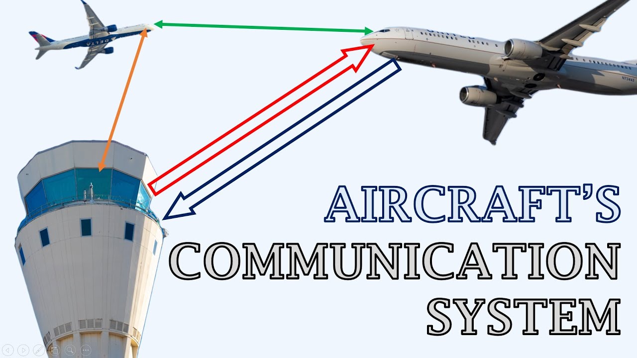
Understanding Aircraft's Communication System | ACARS | Voice & Data | Antennas on an Aircraft!
Airlines Uncovered: Backstage at Qatar Airways Operations
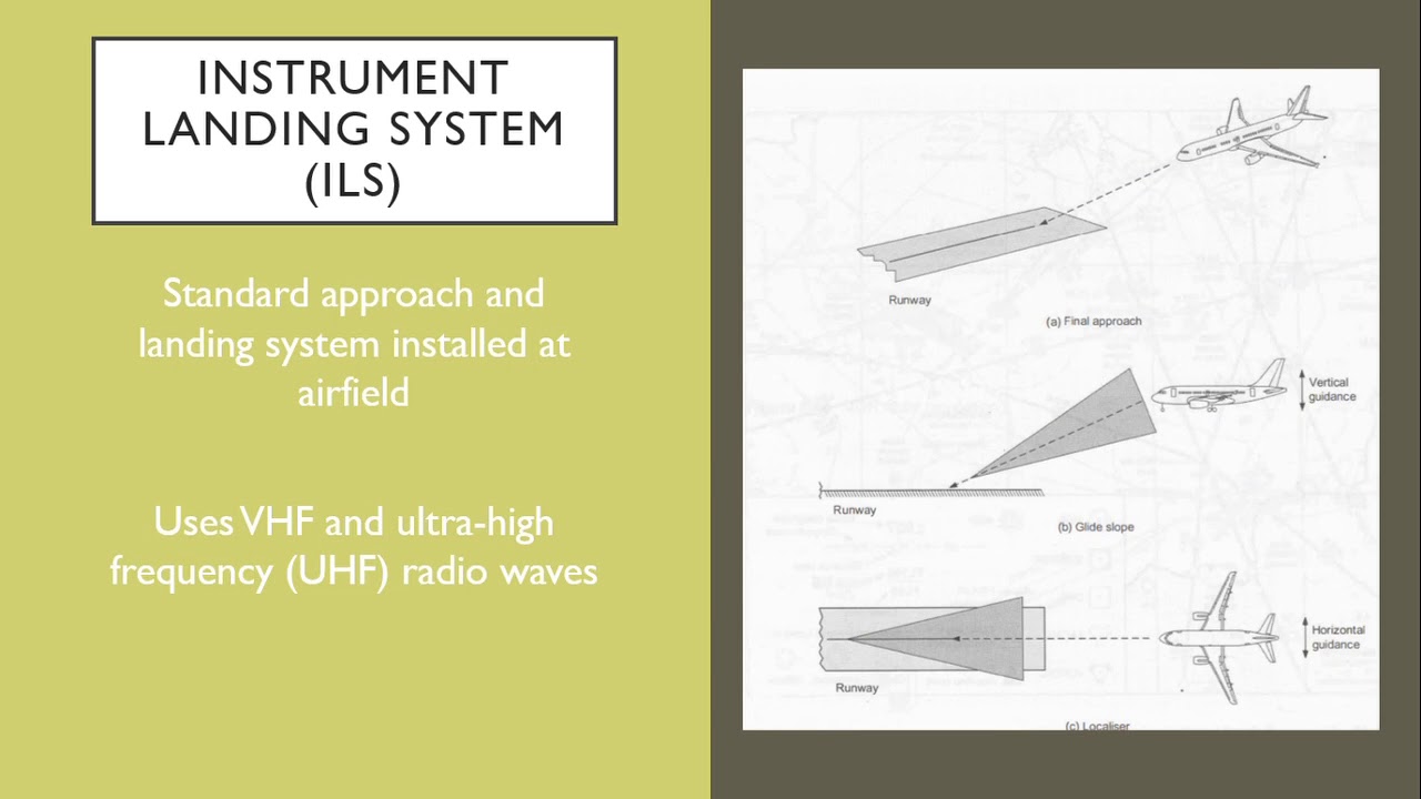
Aircraft Navigation Systems

Airport Secrets: The Mind-Blowing Operation of Qatar Aviation Services

Airbus A320 CBT #008 Auto Flight System - System Presentation

AIR TRAFFIC SERVICES THEORY [ANNEX 11]
5.0 / 5 (0 votes)
