STM32 CAN Communication || NORMAL Mode
Summary
TLDRThis tutorial delves into the intricacies of CAN communication between two devices, using the Blue Pill and F446RE microcontrollers. It covers the setup, including connections and resistors, and explains configuring the CAN peripherals in CubeMX. The script guides through coding, including setting transmission parameters, handling interrupts, and filtering. The practical demonstration shows how to send and receive messages, control LEDs based on received data, and ensure continuous communication without manual intervention, highlighting the efficiency of CAN for embedded systems.
Takeaways
- 😀 The tutorial is a continuation of a series on the CAN (Controller Area Network) protocol, focusing on communication between two CAN devices.
- 🔌 The video demonstrates the hardware setup required for CAN communication, including connections for RX, TX, CAN high, CAN low, and the importance of a 120 ohms resistor at each node.
- 🔩 It's crucial to check if the transceiver breakout board has the necessary 120 ohms resistance, as some do not and require manual connection.
- 🔄 The script explains the software setup using STM32 microcontrollers, specifically the Blue Pill and the F446RE, and the use of CubeMX for configuration.
- 📈 The video covers configuring the CAN peripherals, setting the baud rate to 500,000 bits per second, and the distinction between CAN1 as master and CAN2 as slave.
- 🛠️ The tutorial includes programming steps涉及for transmitting data, such as setting up an interrupt for the RX0, using FIFO for message storage, and handling notifications for data pending in the RX FIFO.
- 💡 The purpose of the project is outlined: the F446RE sends data bytes that control the delay and blink count of an LED on the Blue Pill, which is then mirrored on the F446RE after reception.
- 🔄 The script details the process of sending and receiving messages, including the use of callback functions for handling transmission and reception of data.
- 🛡️ The importance of filter configuration for message passing is emphasized, with specific settings demonstrated for allowing certain IDs through the filter banks.
- 🔧 The video provides practical advice for avoiding confusion with SD card links when connecting multiple controllers to the same computer.
- 🔧 The tutorial concludes with a demonstration of the working system, showing the LED blinking according to the received CAN messages and the data flow captured by an analyzer.
Q & A
What is the purpose of this tutorial video?
-The purpose of this tutorial video is to demonstrate how to communicate between two CAN (Controller Area Network) devices using microcontrollers.
What should viewers do before watching this video?
-Viewers should watch the previous video on the basics of the CAN protocol before watching this one, as it provides necessary foundational knowledge.
What microcontrollers are used in this tutorial?
-The tutorial uses the Blue Pill and the F446RE microcontrollers for the demonstration.
What is the significance of the 120 ohms resistance in the CAN connection?
-The 120 ohms resistance is crucial in the CAN connection as it is connected at each node to ensure proper termination and signal integrity.
How are the CAN high and CAN low wires connected in the setup?
-The CAN high and CAN low wires are connected with each other using a twisted pair to minimize electromagnetic interference.
What is the board rate set to in the CAN configuration?
-The board rate is set to 500,000 bits per second in the CAN configuration.
Which CAN peripheral is configured as the master and which as the slave in the video?
-CAN1 is configured as the master CAN, and CAN2 is configured as the slave CAN in the video.
What is the purpose of the onboard LED and user button in the project setup?
-The onboard LED is used for visual feedback, and the user button is used to trigger the sending of CAN messages when pressed.
How many data bytes can be sent in a single CAN message according to the video?
-Up to 8 data bytes can be sent in a single CAN message.
What is the role of filters in the CAN communication setup shown in the video?
-Filters allow message filtering at the hardware level, reducing the CPU workload by only allowing specific messages to be processed.
How can the communication process be automated without manual button presses?
-The process can be automated by sending data after the LED blinking is finished, as demonstrated with the Blue Pill setup, allowing continuous communication without manual intervention.
Outlines

Этот раздел доступен только подписчикам платных тарифов. Пожалуйста, перейдите на платный тариф для доступа.
Перейти на платный тарифMindmap

Этот раздел доступен только подписчикам платных тарифов. Пожалуйста, перейдите на платный тариф для доступа.
Перейти на платный тарифKeywords

Этот раздел доступен только подписчикам платных тарифов. Пожалуйста, перейдите на платный тариф для доступа.
Перейти на платный тарифHighlights

Этот раздел доступен только подписчикам платных тарифов. Пожалуйста, перейдите на платный тариф для доступа.
Перейти на платный тарифTranscripts

Этот раздел доступен только подписчикам платных тарифов. Пожалуйста, перейдите на платный тариф для доступа.
Перейти на платный тарифПосмотреть больше похожих видео
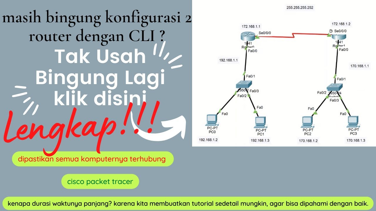
cara konfigurasi 2 router dan 2 switch menggunakan CLI di cisco packet tracer -4 pc saling terhubung
WebRTC in 100 Seconds // Build a Video Chat app from Scratch

How does Bluetooth Work?

Netapp Ontap ports and logical interface ( LIF )
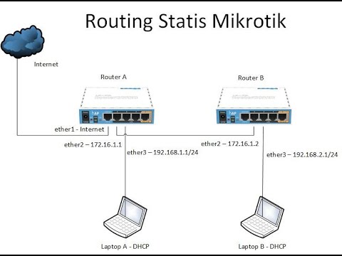
Konfigurasi Routing Statis Mikrotik

Cara membuat jaringan Peer to Peer sederhana || Jaringan Dasar #1
5.0 / 5 (0 votes)
