Praktikum Fisika Dasar - Modul 3 - Rangkaian Kapasitor Paralel
Summary
TLDRThis physics experiment demonstrates the process of working with parallel capacitor circuits. The tutorial guides through the setup, using essential tools like a power supply, jumper cables, and a multimeter. Key steps include connecting the power supply, measuring the voltage across capacitors, and analyzing the behavior of voltages in series and parallel configurations. The experiment highlights the characteristics of capacitors, such as how voltage changes when capacitors are charged and discharged. Participants are encouraged to explore voltage values (V1, V2, and V total) under varying conditions, such as different power settings.
Takeaways
- 😀 The basic physics experiment involves a parallel capacitor circuit and a series capacitor circuit.
- 😀 Essential materials for the experiment include an experiment kit, power supply, jumper cables, and a digital multimeter or voltmeter.
- 😀 The power supply is connected to the experiment kit: red for positive and black for negative terminals, ensuring the switch is turned off initially.
- 😀 V1 represents the voltage across the first capacitor, measured by connecting jumper cables to the correct terminals and the voltmeter's probes.
- 😀 Always set the voltmeter to VDC (DC voltage) mode to properly measure voltage in the circuit.
- 😀 The power supply is turned on, and the voltage on the first capacitor (V1) can be observed on the voltmeter.
- 😀 After turning off the switch, the jumper cables are moved to measure the voltage across the second capacitor (V2).
- 😀 The observed voltage on V2 remains almost the same as the source voltage even when the switch is off, illustrating the capacitor's behavior.
- 😀 To discharge the capacitors and reduce voltage, short-circuit the positive and negative terminals of the capacitor.
- 😀 After discharging, the voltmeter can again be used to observe V2 by turning the switch back on.
- 😀 For total voltage (V total), the voltmeter is connected between points A and B, and the switch is turned on to show the total voltage in the circuit.
- 😀 The experiment requires repeating the steps to measure V1, V2, and V total for power supply voltages of 3V and 6V.
Q & A
What equipment is required for this basic physics experiment?
-The required equipment includes a physics kit, a power supply, jumper cables, and a digital multimeter or voltmeter.
What is the first step when setting up the experiment?
-The first step is to connect the power supply to the experimental kit, ensuring that the positive terminal is connected to the positive part of the kit using a red jumper cable, and the negative terminal is connected to the negative part using a black jumper cable.
Why should the switch on the power supply be turned off initially?
-The switch on the power supply should be turned off initially to prevent any accidental flow of current when setting up the circuit.
How do you measure the voltage across the first capacitor in the parallel capacitor circuit?
-To measure the voltage across the first capacitor (V1), connect the positive probe of the multimeter to the positive side of the capacitor and the negative probe to the negative side of the capacitor.
What is the significance of the switch being turned on for the first capacitor circuit?
-Turning the switch on for the first capacitor circuit allows current to flow and the voltmeter to display the voltage across the capacitor (V1), indicating the potential difference in the circuit.
Why does the voltmeter still show a voltage even when the switch is off?
-Even when the switch is off, the voltmeter may still show a voltage due to the inherent properties of capacitors, which can retain charge and maintain a voltage across them for some time.
How can you discharge the voltage across the capacitor?
-To discharge the voltage across the capacitor, you can short the positive and negative terminals of the capacitor, effectively neutralizing the stored voltage.
What happens when you switch on the second capacitor circuit?
-When the switch for the second capacitor circuit is turned on, the voltmeter will display the voltage across the second capacitor (V2). This indicates the voltage at the second capacitor when the circuit is active.
How do you measure the total voltage (V total) across both capacitors?
-To measure the total voltage (V total) across both capacitors, switch the probes of the voltmeter from the individual capacitors to the combined points of the parallel circuit and observe the displayed voltage.
What should you do when changing the voltage source from 3V to 6V?
-When changing the voltage source to 6V, repeat the same procedure for measuring the voltages across the capacitors (V1, V2, and V total) to observe how the voltages change with the increased supply voltage.
Outlines

Этот раздел доступен только подписчикам платных тарифов. Пожалуйста, перейдите на платный тариф для доступа.
Перейти на платный тарифMindmap

Этот раздел доступен только подписчикам платных тарифов. Пожалуйста, перейдите на платный тариф для доступа.
Перейти на платный тарифKeywords

Этот раздел доступен только подписчикам платных тарифов. Пожалуйста, перейдите на платный тариф для доступа.
Перейти на платный тарифHighlights

Этот раздел доступен только подписчикам платных тарифов. Пожалуйста, перейдите на платный тариф для доступа.
Перейти на платный тарифTranscripts

Этот раздел доступен только подписчикам платных тарифов. Пожалуйста, перейдите на платный тариф для доступа.
Перейти на платный тарифПосмотреть больше похожих видео

Fisika Kelas 12 - Rangkaian Kapasitor SERI dan PARALEL

Capacitors in Series and Parallel Explained!

Capacitor Explained : Calculations | Series | Parallel | Charging | Discharging
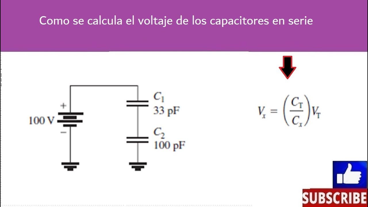
Voltaje de capacitores en serie
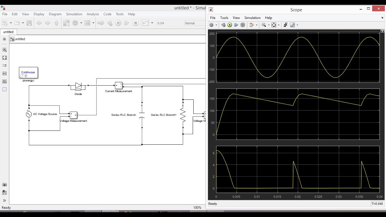
Half Wave Unctrolled Rectifier with C filter Matlab Simulink

Resistors in Series and Parallel Circuits Experiment - GCSE Physics Required Practical
5.0 / 5 (0 votes)
