RC and RL Circuits
Summary
TLDRThis video demonstrates the principles of RC and RL circuits through both theoretical explanations and practical experiments. The RC circuit, consisting of a resistor, capacitor, and power source, explores charge accumulation, time constants, and half-life. The RL circuit, with a resistor, inductor, and power source, covers current buildup, inductive behavior, and the related half-life. The experiments involve adjusting equipment like signal generators and oscilloscopes to measure charge and voltage decay patterns, with the half-lives for the RC and RL circuits measured at 0.8 milliseconds and 16 microseconds, respectively.
Takeaways
- 😀 The RC circuit consists of a resistor, capacitor, and power source, and the charge on the capacitor changes over time according to a differential equation derived from Kirchhoff's Voltage Law.
- 😀 The time constant (τ) of the RC circuit is defined as the product of resistance (R) and capacitance (C), and it determines how quickly the capacitor charges or discharges.
- 😀 The half-life of the capacitor charge or voltage in the RC circuit is the time it takes for the charge to drop to half its saturation value and is calculated as τ * ln(2).
- 😀 In the RC circuit experiment, a square wave signal is used, alternating between V₀ and zero, to observe the capacitor's charging and discharging behaviors.
- 😀 Frequency adjustments are crucial in the RC circuit experiment to allow the capacitor enough time to charge or discharge fully, affecting the observed voltage patterns.
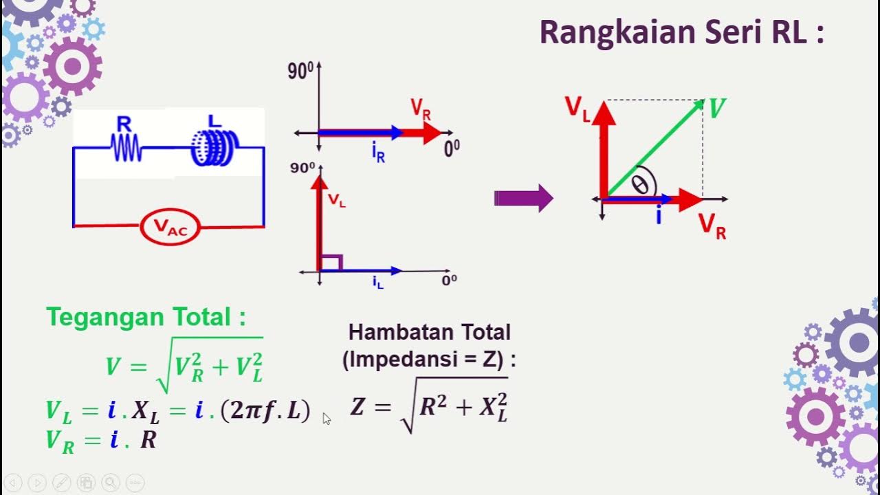
- 😀 The RL circuit consists of a resistor, inductor, and power source, with the inductor's voltage being related to the derivative of the current.
- 😀 In the RL circuit, the time constant (τ) is calculated as L/R, where L is inductance and R is resistance, and it determines how quickly the current reaches its saturation value.
- 😀 Initially, when the power is applied to the RL circuit, the inductor acts as an infinite resistor, blocking current flow. As time progresses, the current increases to its saturation value.
- 😀 The behavior of the RL circuit is frequency-dependent, and higher frequencies may be needed to observe a proper decay pattern for voltage or current changes.
- 😀 In both circuits, measurements of the half-life help determine the time it takes for the charge or current to decay to half of its initial value, aiding in the understanding of circuit behavior.
Q & A
What are the components of an RC circuit?
-An RC circuit consists of a resistor (R), a capacitor (C), and a power source.
How is the time constant (τ) of an RC circuit defined?
-The time constant (τ) of an RC circuit is defined as the product of the resistance (R) and capacitance (C), i.e., τ = RC.
What is the significance of the saturation value (Q0) in an RC circuit?
-The saturation value (Q0) in an RC circuit represents the maximum charge that the capacitor can hold when fully charged.
What does the term 'half-life' refer to in the context of an RC circuit?
-In an RC circuit, the half-life refers to the time it takes for the charge or voltage across the capacitor to decrease to half of its saturation value.
What is the formula for calculating the half-life in an RC circuit?
-The half-life in an RC circuit is calculated as the time constant (τ) multiplied by the natural logarithm of 2, i.e., half-life = τ * ln(2).
How does the frequency of the input signal affect the behavior of an RC circuit?
-The frequency of the input signal influences how effectively the capacitor charges and discharges. If the frequency is too high, the capacitor cannot fully charge or discharge, leading to incomplete voltage patterns.
What happens when a square wave signal is applied to an RC circuit?
-When a square wave signal is applied to an RC circuit, the capacitor alternately charges and discharges as the voltage switches between its maximum value and zero.
What is the time constant (τ) in an RL circuit, and how is it defined?
-In an RL circuit, the time constant (τ) is defined as the ratio of the inductance (L) to the resistance (R), i.e., τ = L/R.
How does an inductor behave at time 0 in an RL circuit?
-At time 0, the inductor behaves like an infinite resistor, meaning no current passes through the circuit, and all the applied voltage is across the inductor.
What is the effect of a square wave signal on the RL circuit?
-When a square wave signal is applied to an RL circuit, the voltage across the inductor initially increases as the current builds up. When the voltage is turned off, the inductor's voltage quickly drops and then decays over time.
Outlines

Этот раздел доступен только подписчикам платных тарифов. Пожалуйста, перейдите на платный тариф для доступа.
Перейти на платный тарифMindmap

Этот раздел доступен только подписчикам платных тарифов. Пожалуйста, перейдите на платный тариф для доступа.
Перейти на платный тарифKeywords

Этот раздел доступен только подписчикам платных тарифов. Пожалуйста, перейдите на платный тариф для доступа.
Перейти на платный тарифHighlights

Этот раздел доступен только подписчикам платных тарифов. Пожалуйста, перейдите на платный тариф для доступа.
Перейти на платный тарифTranscripts

Этот раздел доступен только подписчикам платных тарифов. Пожалуйста, перейдите на платный тариф для доступа.
Перейти на платный тарифПосмотреть больше похожих видео

Electrical Engineering: Ch 8: RC & RL Circuits (1 of 43) RC & RL Circuits Introduction
Rangkaian Seri RL-RC-LC dengan Sumber AC
Watch electricity hit a fork in the road at half a billion frames per second

Dasar Teknik Elektro - Seri Pembagi Tegangan

Peluang • Part 1: Percobaan, Ruang Sampel, Kejadian, dan Peluang Suatu Kejadian

Part 3 Pembahasan Soal Ujian Sekolah US IPA Fisika SMP
5.0 / 5 (0 votes)
