How Computers Calculate - the ALU: Crash Course Computer Science #5
Summary
TLDRIn this Crash Course Computer Science episode, Carrie Ann explores the Arithmetic and Logic Unit (ALU), the 'mathematical brain' of a computer. She explains how the ALU, using logic gates like AND, OR, NOT, and XOR, performs fundamental operations like addition. The video delves into constructing a simple ALU circuit, starting from a half adder to a full adder, and culminating in an 8-bit ripple carry adder. It also touches on overflow, the ALU's logic unit, and the importance of operation codes and flags in computing. The episode concludes with a nod to the Intel 74181 ALU and sets the stage for future discussions on memory.
Takeaways
- 🧠 The Arithmetic and Logic Unit (ALU) is the mathematical brain of a computer, responsible for all computations.
- 🏗️ The Intel 74181, released in 1970, was a groundbreaking ALU as it was the first to fit entirely on a single chip.
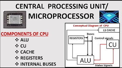
- 🔢 The ALU is composed of two main units: the arithmetic unit for numerical operations like addition and subtraction, and the logic unit for logical operations.
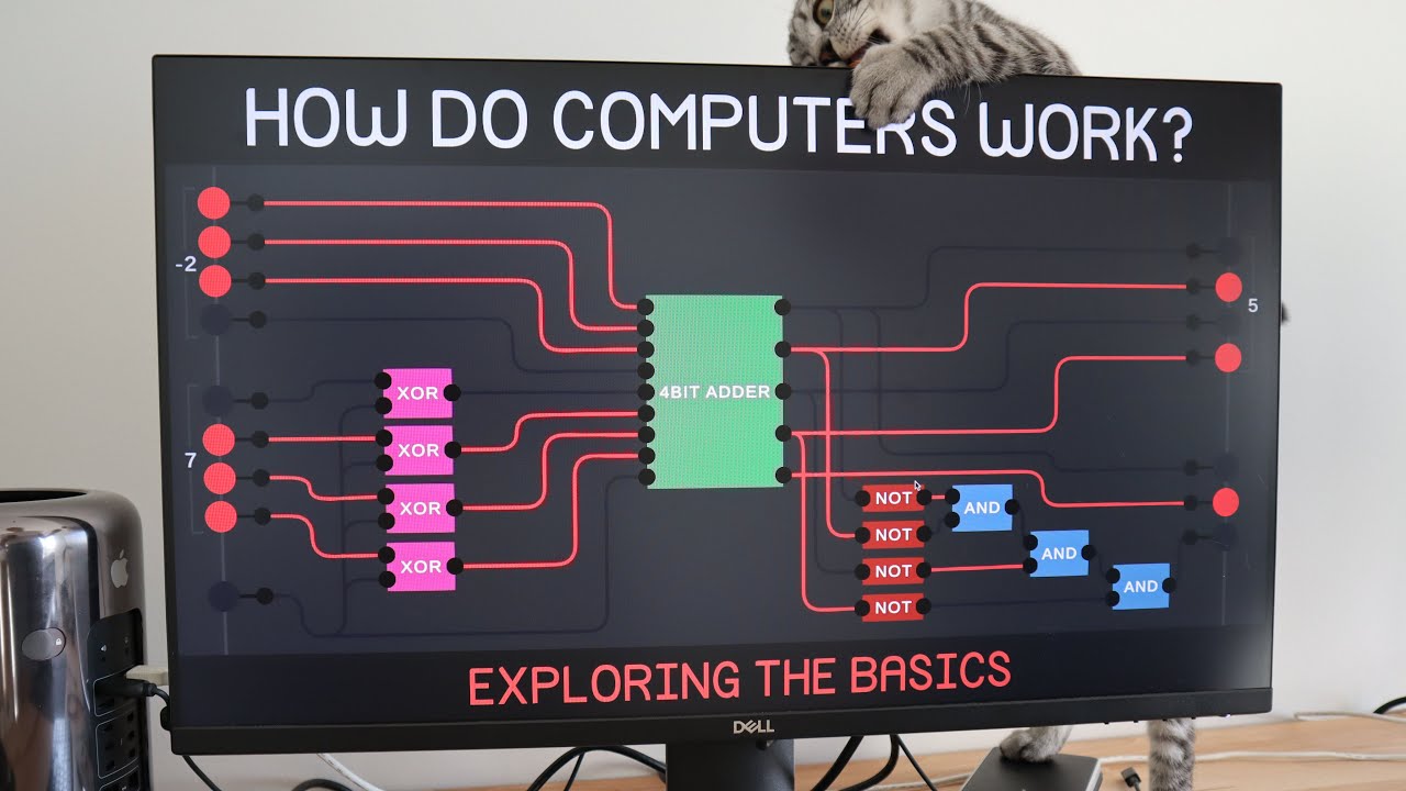
- ⚙️ Basic arithmetic operations are built using logic gates such as AND, OR, NOT, and XOR, starting with simple circuits like the half adder.
- 🔀 The full adder is an extension of the half adder, capable of handling carry bits from previous calculations, essential for multi-bit addition.
- 🌊 The 8-bit ripple carry adder is a chain of full adders that process carry bits sequentially, though it can be slow due to the ripple effect.
- 🚫 Overflow occurs when the result of an addition exceeds the capacity of the bits being used, which can cause errors, as famously demonstrated by the Pac-Man arcade game bug.
- 💡 Modern computers use 'carry-look-ahead' adders for faster computation, reducing the time it takes for carry bits to propagate.
- 🔄 Simple processors perform multiplication through repeated additions, while more advanced ones have dedicated circuits for faster multiplication.
- 🏁 The ALU also includes a logic unit for operations like AND, OR, NOT, and checks for conditions like zero or negative values.
- 📋 ALUs use operation codes to determine the type of operation to perform and output flags to indicate statuses like zero, negative, or overflow.
Q & A
What is the primary function of an ALU?
-An ALU (Arithmetic and Logic Unit) is responsible for performing all of the computation in a computer, including arithmetic operations like addition and subtraction, as well as logical operations like AND, OR, and NOT.
What is the significance of the Intel 74181 ALU?
-The Intel 74181 was a groundbreaking ALU when it was released in 1970 because it was the first complete ALU that fit entirely inside a single chip, which was a significant engineering achievement at the time.
How does a half adder work?
-A half adder takes two binary digits (bits) as inputs and produces a sum output. It uses an XOR gate to determine the sum and an AND gate to determine if there is a carry bit, which occurs only when both inputs are 1.
What is the purpose of a full adder in an ALU?
-A full adder is used to add three bits together, including the carry bit from the previous less significant bit addition. It combines the functionality of a half adder with additional logic to handle the carry input and produce both a sum and a carry output.
What is an 8-bit ripple carry adder?
-An 8-bit ripple carry adder is a circuit that adds two 8-bit numbers together by using a series of full adders. The carry bits 'ripple' through each full adder stage, adding each bit pair and passing the carry to the next stage.
What causes an overflow in an ALU?
-An overflow occurs when the result of an addition is too large to be represented by the number of bits being used. For example, adding two numbers that result in a value that exceeds what can be stored in an 8-bit system.
How does the original PacMan arcade game relate to ALU overflows?
-The original PacMan arcade game used an 8-bit system to track levels, and when a player reached level 256, which is beyond the maximum storable value in 8 bits (255), the ALU overflowed, causing errors and glitches, making the level unbeatable.
What is a carry-look-ahead adder and why is it used in modern computers?
-A carry-look-ahead adder is a faster circuit used in modern computers for adding binary numbers. It reduces the delay caused by the ripple carry effect in traditional adders by looking ahead to determine carry values before they are needed.
How does an ALU perform multiplication without a dedicated circuit?
-Simple ALUs without a dedicated multiplication circuit perform multiplication by using a series of additions. For example, to multiply 12 by 5, an ALU would add 12 to itself 5 times.
What are the three universal and frequently used flags in an ALU?
-The three universal and frequently used flags in an ALU are the Zero Flag, the Negative Flag, and the Overflow Flag. These flags indicate the status of the result after an arithmetic operation, such as whether the result is zero, negative, or too large to be represented within the given number of bits.
Outlines

Этот раздел доступен только подписчикам платных тарифов. Пожалуйста, перейдите на платный тариф для доступа.
Перейти на платный тарифMindmap

Этот раздел доступен только подписчикам платных тарифов. Пожалуйста, перейдите на платный тариф для доступа.
Перейти на платный тарифKeywords

Этот раздел доступен только подписчикам платных тарифов. Пожалуйста, перейдите на платный тариф для доступа.
Перейти на платный тарифHighlights

Этот раздел доступен только подписчикам платных тарифов. Пожалуйста, перейдите на платный тариф для доступа.
Перейти на платный тарифTranscripts

Этот раздел доступен только подписчикам платных тарифов. Пожалуйста, перейдите на платный тариф для доступа.
Перейти на платный тарифПосмотреть больше похожих видео

The Central Processing Unit (CPU): Crash Course Computer Science #7
Exploring How Computers Work
CPU and Its Components|| Components of MIcroprocessor

2. Arsitektur Komputer Struktur CPU

CPU - Organisasi dan Arsitektur Komputer

IGCSE Computer Science 2023-25 - Topic 3: HARDWARE (1) - COMPUTER ARCHITECTURE - Von Neumann & CPU
5.0 / 5 (0 votes)
