L 01 Brief Introduction of Computer Aided Design | Computer Aided Design | Mechanical
Summary
TLDRThe lecture introduces the subject of Computer-Aided Design (CAD) for mechanical engineering students, covering six key chapters: introduction, curves and surfaces, mathematical representation of solids, geometric transformation, finite element analysis, and engineering optimization. It emphasizes the importance of understanding design, problem-solving, and the distinction between design and manufacturing. Students are encouraged to learn modeling and analysis software like SolidWorks and ANSYS to enhance their skills in 3D modeling and optimization. The session highlights the need to master orthographic and isometric projections and lays a foundation for future classes on CAD concepts.
Takeaways
- 📘 The subject being introduced is Computer-Aided Design (CAD) with six chapters covering a wide range of topics.
- 🖥️ Students will study graphic display devices such as LCD and LED in the introduction chapter.
- 📐 In the chapter on curves and surfaces, students will learn about different types of curves (hyperbola, parabola) and surfaces (analytical and synthetic).
- 🔢 The third chapter focuses on the mathematical representation of solids using software like SolidWorks, AutoCAD, and Creo for 3D design.
- 🔄 Geometric transformations, including translation and rotation of objects, are the focus of the fourth chapter.
- 🔧 The fifth chapter covers Finite Element Analysis (FEA), where students will learn how to solve problems related to structures like beams and deformation.
- 🚀 The final chapter on Engineering Optimization focuses on solving problems using optimization techniques.
- 🎯 The definition of design for mechanical engineers includes creating new designs or modifying existing systems.
- 📊 CAD involves both design (creating and drafting) and manufacturing (deciding processes like turning and machining).
- 📐 Understanding orthographic (front, top, side views) and isometric projections is crucial for 3D modeling in CAD software.
Q & A
What is the primary focus of the 'Computer Aided Design' subject?
-The primary focus is to understand six main chapters, including introduction, curves and surfaces, mathematical representation of solids, geometric transformation, finite element analysis, and engineering optimization.
What is the role of 'Geometric Transformation' in this course?
-Geometric transformation refers to moving an image from one position to another, which includes operations like translation (moving objects), rotation, and scaling.
What kind of problems are addressed in the 'Finite Element Analysis' chapter?
-In this chapter, students solve various problems such as beam analysis under distributed loads, calculating deformation, and understanding structural responses.
How is 'Engineering Optimization' defined in this subject?
-Engineering optimization involves finding the best solution to a problem using various optimization methods, with a focus on improving designs or systems.
What are the key topics covered in the 'Introduction' chapter of the subject?
-The 'Introduction' chapter covers basic concepts such as different types of graphic display devices (e.g., LCD, LED), pixel resolution, and understanding the product cycle, including both conventional and computer-aided approaches.
What are 'Curves and Surfaces' in the context of computer-aided design?
-This chapter explains the design of various curves like hyperbolas, parabolas, and ellipses, along with surfaces such as analytical and synthetic surfaces. These are crucial for 3D modeling.
How is 'Mathematical Representation of Solids' applied in CAD?
-It involves creating a 3D object using software like SolidWorks, AutoCAD, and Creo. This chapter teaches students how to design and represent solids mathematically in software.
What is the difference between 'Orthographic' and 'Isometric' views in design?
-Orthographic views represent different perspectives of a 3D object like front, top, and side views, whereas isometric views combine these perspectives to create a 3D model.
What software tools are recommended for students in this course?
-Students are advised to learn modeling software like SolidWorks and analysis software like ANSYS, as they are widely used in industry for 3D modeling and performing various analyses.
What is the significance of the 'Design Process' for mechanical engineers?
-The design process involves identifying a problem, researching and exploring solutions, creating a prototype, testing it, and refining the solution. Mechanical engineers use this systematic approach to develop or improve products.
Outlines

Этот раздел доступен только подписчикам платных тарифов. Пожалуйста, перейдите на платный тариф для доступа.
Перейти на платный тарифMindmap

Этот раздел доступен только подписчикам платных тарифов. Пожалуйста, перейдите на платный тариф для доступа.
Перейти на платный тарифKeywords

Этот раздел доступен только подписчикам платных тарифов. Пожалуйста, перейдите на платный тариф для доступа.
Перейти на платный тарифHighlights

Этот раздел доступен только подписчикам платных тарифов. Пожалуйста, перейдите на платный тариф для доступа.
Перейти на платный тарифTranscripts

Этот раздел доступен только подписчикам платных тарифов. Пожалуйста, перейдите на платный тариф для доступа.
Перейти на платный тариф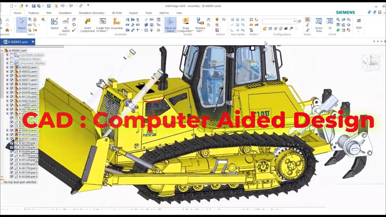


5.0 / 5 (0 votes)
