Introduction to UML
Summary
TLDRIn this introduction to UML (Unified Modeling Language), Tomas Eden, a senior consultant in embedded systems from Stockholm, Sweden, provides an overview of UML's purpose and utility. UML is a visual modeling language primarily for software systems, with 14 types of diagrams to capture different aspects of a system. The video focuses on three key diagrams: Class Diagrams for structure, State Machines for behavior, and Sequence Diagrams for interactions. Eden emphasizes UML's role in system design, documentation, and code generation, and suggests starting with basic diagrams before exploring advanced ones. He also recommends tools for UML modeling, from whiteboards to specialized software like IBM Rational Rhapsody and Enterprise Architect.
Takeaways
- 😀 UML (Unified Modeling Language) is a visual modeling language used primarily for software systems, but can also be applied to systems engineering.
- 🔍 The goal of UML is to provide a standard way to visualize the design of a system, making it easier to understand and communicate.
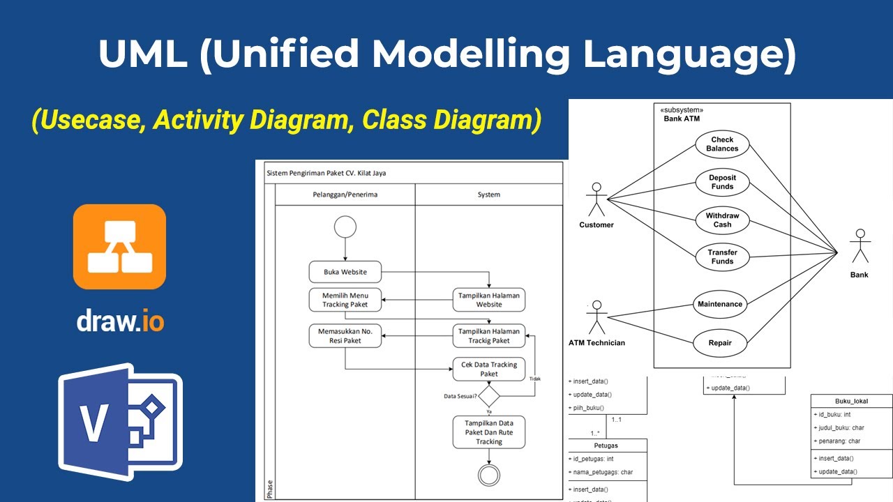
- 📊 UML includes 14 different types of diagrams, each capturing different aspects of a software system, such as structure, behavior, and interactions.
- 🛠️ UML can be particularly beneficial for object-oriented programming languages, although it can be used for non-object-oriented systems as well.
- 🔨 One of the main uses of UML is in the design phase of system development, before coding begins, to help plan out the system's structure and behavior.
- 🔄 UML diagrams can be used to document a system, making it easier to maintain and understand, especially in organizations with large amounts of legacy code.
- 🔍 The Class Diagram is a key UML diagram that shows the classes in a system, their attributes, operations, and the relationships between them.
- 🔄 The State Machine Diagram is used to model the behavior of a system by defining states, transitions, and actions, which can help avoid complex and hard-to-follow code.
- 🔗 The Sequence Diagram is an interaction diagram that shows the interactions between objects in a system over time, which is useful for modeling and testing protocols.
- 🛠️ Tools for creating UML diagrams range from simple whiteboards to sophisticated software tools like IBM Rational Rhapsody and Enterprise Architect, with various features and price points.
- 📚 Learning UML can be beneficial for software designers and developers, as it provides a structured way to think about and design software systems.
Q & A
What is the primary goal of the UML introduction presented by Tomas Eden?
-The primary goal is to provide an initial insight into what UML (Unified Modeling Language) is and to determine if it could be beneficial for the viewer and their organization.
What is UML used for according to the presentation?
-UML is used for modeling software systems, and it can also be applied to systems engineering. It is particularly useful for designing systems before coding and for documenting the system architecture.
How many types of diagrams are specified in the UML standard?
-There are 14 different types of diagrams specified in the UML standard.
What are the two main groups of UML diagrams?
-The two main groups of UML diagrams are structural diagrams and behavior diagrams.
What is a class diagram and why is it useful?
-A class diagram is a structural diagram that shows the classes, their attributes, methods, and the relationships between them. It is useful for providing a clear overview of the system's structure and for designing object-oriented systems.
How does a state machine diagram help in modeling software systems?
-A state machine diagram helps in modeling software systems by describing the logical structure and behavior of the system through states, transitions, and actions, which can prevent the code from becoming disorganized.
What is the difference between a sequence diagram and a state machine diagram?
-A sequence diagram is an interaction diagram that shows the interactions between objects in a system over time, while a state machine diagram is a behavior diagram that focuses on the states an object can be in and the transitions between those states.
What is the role of the 'guard' in a state machine diagram?
-In a state machine diagram, a guard is a condition that must be true for a transition to occur. It acts as an exit statement that needs to be satisfied for the transition to be executed.
Why might a sequence diagram be preferred over a state machine diagram?
-A sequence diagram might be preferred when dealing with multiple components or when the system involves complex interactions between objects, as it can better illustrate the sequence of messages and the flow of control.
What are some tools recommended for creating UML diagrams?
-Some recommended tools for creating UML diagrams include whiteboards for initial design discussions, Visio for basic diagramming, and more advanced tools like IBM Rational Rhapsody or Sparx Systems Enterprise Architect for code generation and reverse engineering.
What is the significance of the multiplicity numbers in a class diagram?
-The multiplicity numbers in a class diagram indicate the number of instances one class can have in relation to another class, showing the relationship's cardinality.
Outlines
📘 Introduction to UML
The speaker, Tomas Eden, introduces the Unified Modeling Language (UML) as a visual modeling language primarily used for software systems. He clarifies that the presentation aims to provide an initial understanding of UML rather than an exhaustive tutorial. UML is used for creating diagrams that capture various aspects of a software system, and it's particularly beneficial for object-oriented programming. The presentation mentions that UML can be applied in system design before coding begins, and it can also be used for documentation and reverse engineering of legacy code. The UML standard includes 14 different types of diagrams, but the speaker focuses on three main types: structural, behavioral, and interaction diagrams.
🚗 Class Diagrams in UML
The speaker explains class diagrams as a structural diagram in UML, using a car and its components as an example. Classes in object-oriented programming encapsulate data and functions. The class diagram shows class names, member variables (attributes), and operations (methods). Attributes can be public or private, indicated by a '+' or '-' sign, respectively. Operations are typically public and do not have a lock symbol. Associations between classes represent relationships, with multiplicity numbers indicating the number of instances. Composition and aggregation are specific types of associations, shown with a filled diamond shape, indicating that the life cycle of the associated classes is tied to the owning class. Generalizations, or inheritance, are shown with arrows, indicating that a class is a type of another class.
🔐 State Machines in UML
The speaker discusses state machines as a type of behavioral diagram in UML, illustrating with a safe lock example. State machines describe the logical structure of code, defining states, transitions, and actions. States represent conditions, and transitions occur based on events (triggers) and conditions (guards). The example shows nested states within the 'safe closed' state, including 'lock idle' and 'waiting for more digits'. Transitions can have actions, such as sending a message or changing a state variable. The speaker also mentions special internal triggers like 'on entry' and 'on exit' for states, which are executed when entering or exiting a state.
🔁 Sequence Diagrams in UML
The speaker introduces sequence diagrams as a type of interaction diagram in UML, focusing on a model-view-controller pattern example. Sequence diagrams show the interactions between objects over time, represented by lifelines. Messages between objects are shown as arrows, indicating communication. The example includes a user creating an account, with the view sending a 'create user request' message to the controller. The speaker discusses the use of sequence diagram references to manage complexity and combined fragments, which are used to represent conditional logic within interactions. The comparison between sequence diagrams and state machine diagrams is highlighted, with the former being more suitable for multiple components and the latter for control flows without a clear endpoint.
🛠️ UML Tools and Conclusion
The speaker concludes by discussing various UML tools, recommending starting with a whiteboard for simplicity and then progressing to digital tools for documentation. He mentions Visio as a basic tool, Microsoft's diagramming tools in Visual Studio, and IBM's Rational Rhapsody for more advanced features like code generation and reverse engineering. The speaker also highlights the Rational Modeler as a free alternative for creating UML diagrams. He encourages learning the basics of UML and using it within organizations before exploring more complex diagram types. The presentation ends with an invitation for questions and potential training courses.
Mindmap
Keywords
💡UML (Unified Modeling Language)
💡Diagrams
💡Class Diagram
💡State Machine Diagram
💡Sequence Diagram
💡Object-Oriented Programming
💡Inheritance
💡Multiplicity
💡Association
💡Tools
Highlights
Introduction to UML by Tomas Eden, a senior consultant in embedded systems based in Stockholm, Sweden.
The goal of the presentation is to provide an insight into UML and its applicability for organizations, not to teach everything about UML.
UML (Unified Modeling Language) is primarily used for modeling software systems, although it can also be applied to systems engineering.
UML consists of 14 different types of diagrams, each capturing different facets of a software system.
Three main types of UML diagrams introduced: structural diagrams (like class diagrams), behavior diagrams (like state machines), and interaction diagrams (like sequence diagrams).
Class diagrams in UML show the structure of a system by representing classes, their attributes, methods, and relationships like associations and inheritance.
State machine diagrams are used to model the logical flow of a system, showing states and transitions between them based on conditions.
Sequence diagrams are used to represent interactions between objects over time, particularly useful for modeling protocols and complex interactions.
The importance of starting system design with UML diagrams to ensure a clear structure before beginning code implementation.
UML can be used to generate code from diagrams, ensuring that design and implementation are always in sync.
Reverse engineering tools are available to create UML diagrams from existing code, which is useful for documenting legacy systems.
Using UML in an organization requires a basic understanding among all team members, with further diagram types introduced as organizational maturity increases.
Recommendations on UML tools: starting with whiteboard designs, moving to tools like Microsoft Visio, IBM Rational Rhapsody, or Sparx Systems Enterprise Architect for more advanced needs.
The value of UML for documentation purposes, especially in structured organizations where maintaining up-to-date documentation is critical.
The presentation concludes with an invitation for further questions, additional presentations, and potential training courses.
Transcripts
hello welcome to this introduction to
UML the unified modeling language my
name is Tomas Eden and I'm a senior
consultant in embedded systems right
here in Stockholm Sweden the goal of
this introduction is not to teach you
everything about UML but simply to give
you a first insight into what UML is and
if it could be something for you and
your organization this presentation in
just the first mysterious the
presentation is about UML if you have
any questions please get in touch or
watch the upcoming presentations so
let's dive right in so what is you know
just as the name says it's a modeling
lounge and it's a modeling lounge for
most for software systems it can be used
for systems engineering also where the
next station causes Mel but today I am
only going to talk about how to can be
used for modeling software systems you -
the visual modeling lounge and what I
mean with that is that you're working
with different types of diagrams you can
do this either in just the whiteboard or
in a modeling program specialized for
you Mel
I like it back to view those tools at
the end of this presentation
in the Yuma standard there are 14
different types of diagrams specified
and each and then pressed capture
different facets of our software system
today I'm going to introduce to you
three of these different diagrams to
give you a feel for what can be done
with UML many of today's programming
languages are object-oriented
programming lounges and so is you know
UML can definitely also be used to model
non object-oriented systems but you do
get more mileage shattered if your
software system is also object-oriented
now that we basically know what UML is
the next question is what can it be used
for I'd say that the most common way to
use the UML is when designing systems
and before you start tacking code if
you're in a larger organization and you
have different systems departments from
the development departments the systems
departments would draw up some UML
diagrams showing the use cases of the
whole system
and the deployment of different
subsystems and
four components they may also specify
the protocols between subsystems getting
over to the engineers boom actually
implementation they would break down
these UML diagrams into smaller parts
and I detailed down to the class and
object level of the design before before
starting to write code if you're really
serious about using a UML you can even
generate the actual code from the UML
diagrams themselves the benefits here
are that the design and the
implementation are always in sync and by
increasing the abstraction level you can
potentially become more efficient every
software designer knows that their
system needs to be documented in the end
but even the most structured
organizations the state of the
documentation is most often too little
and too late if you have designed your
system in UML you already have a
high-level visual description on your
system I had some clarifying text and
you're done if you're having to sign
into your system in email from the
beginning or if you have a large amount
of legacy code there are tools there for
you to reverse engineer your code into
UML diagrams or if you're guaranteeing
your documentation from code comments in
for example the doxygen style there are
plugins to define UML diagrams directly
in the comments now our two the
different diagram types as I said before
Humana consists of 14 different diagrams
I'm not going to explain all of them now
but don't worry I'm going to go through
most of the diagrams deeply in the
upcoming presentations but let's look a
bit closer at the different groups of
diagrams first of all we can see that
the UML diagrams are divided into two
different main groups on the Left we
have the structural diagrams these
diagrams are very static and most of
them make sure the different components
building up the systems and how they
relate to each other the components I'm
talking about color for example nodes
executables classes were objects
right we have the behavior diagrams they
show more what is happening during a
runtime they basically show the logic as
it is implemented and how the system
reacts to stimuli a subgroup of the
behavior diagrams are the interaction
diagrams while the other behavior
diagrams show the behavior within a
component interaction diagrams show
behavior between components they could
for example describe how the
client-server react to each other's
inputs over an interface I'm going to go
through one diagram each from these
three groups and I'm going to start with
a scratching diagram the class diagram
so here we have the class diagram for
this example I have prepared a class
diagram over a car and some of its
components each box here is a class in
object-oriented programming a class
isn't an encapsulation of date and
functions in that data this is exactly
what we have here also first when the
class name in this case car below that
where that commute as do you male speak
for member variables in this case we
have that imbued gas that repente
represents sandwich gas there is in the
car then below with that we have
operations
let's wrote in that what so now that
languages are called methods or memory
functions here we have fill for filling
out the car or the gas and start for
starting the car you see that small
block in the gas attribute that shows
that the attribute is private this means
then that rent that that would get isn't
accessible from outside of the class the
operation of this class don't have a
lock and therefore are public you can
also often see a plus sign for the
public attributes and/or operations and
the minus sign for those that are prior
to then we have these lines between the
classes that are all over the place
these are associations an association
signifies a relationship between two
classes ever example we have an
association to an engine and the
transmission
the number at each end is the
multiplicity the left-hand number who
said that each transmission knows about
one engine and with the right-hand
number we say that each engine knows
about one transmission a general
Association is a very fuzzy way to
describe the relationship there are a
few more specific associations one which
is called a composition or a composition
aggregation this signifies that if an
object of an oni class is destroyed so
is the owned class this filled in
diamonds at the car class shows that it
is composed of one engine one
transmission and four wheels if the car
is destroyed so is the engine of the
transmission and the wheels now we only
have one more things thing to explain
here and that's the arrows you here at
the bottom these are called
generalizations which is the same thing
as what is usually called inheritance in
a programming language that is to say
that one class is a type of another
class in this case we have a
transmission as a base class this base
class is a generalization of the derived
classes for manual transmission and
automatic transmission or we could say
that the manual and automatic
transmission classes are inheriting from
the transmission class in this example I
shown the differences between the manual
automatic transmission classes in that
the shift operation is public in the
manual class and private in the
automatic
class as you can see it's very easy to
get an overview of a class diagram and
how the different classes are related to
each other
for a developer it is also very much
faster to hash out class diagrams on a
white board than it is direct number of
class declarations in code so we're
starting developing a new feature I'd
highly recommend starting with the
growing up a class diagram to get a
feeling for the structure so that was
the class diagram now let's move
directly over to behavior diagram the
state machine a state machine is a
classical way to describe the logical
structure
a great way to code in a way that
doesn't end up looking like spaghetti
instead of having lots of variables
define different cases we specified
states we move between depending on the
state we are in we get different
behavior so here we have a type a
mistake machine for safe a safe can have
two basic states it can either be locked
or it can be open on the stake we have
lock this safe as a numeric pad and then
an unlock button the IDs that yeah you
first punch in your code and then press
the unlock button among that we can the
state machine and have nested states
within other states
so when within the state safe closed we
have two other states look idle and
waiting for more digits to get between
the different states we have transitions
all conversations have a trigger that is
the event that forces the transition
that to be evaluated but then it also
has a guard there this is an exit
statement that needs to be true for the
transition would be cared through it
could be letter lock the variable needs
to have a certain value for example so
if the trigger has happened and the
guard is true then you move from one
state state to another a transition can
as nay as an extra bonus also have side
effects for example it can send a
message to another system we call this
side effect an action so let's try to
see if we can move through the state
machine each state machine has a
starting point
this is signified as the transition
coming from a round ring we see that at
the top of the screen here so you start
in this state safe closed then because
this state has nested states we also
have a nested starting point we see that
starting point go into the lock idle
State from the lock state we have lock
idle state we only have one outgoing
transition and that is triggered by a
digit being entered into the number
but luck is that only requires a
password a one-digit is a pretty poor
lock so that transition takes us in the
state where we are waiting for more
digits this state you also see the text
digit entered now this is an indication
that we within this state also are
waiting for the trigger digit entered
but that if this trigger comes it does
not change the state will handle it we
call this a do action there are so two
it there are also two more special
internal triggers called on entry and on
exit which are executed when entering a
state and exiting a state but I'll talk
more about those in an in another
presentation anyway we stay in the
waiting for a more deep state until
somebody presses the open button and
here you see that depending on the value
of the guard in this case if the correct
code wasn't Herman or not we follow two
different transitions if the incorrect
code was entered we are back in the lock
idle state if instead of the correct
code was entered we performed action
Lock disengaged and move out of our
nested state and into the safe open
state there is only one way out of the
safe open state and that is by pressing
the close button under the condition
when the door is closed this then
performs the action of engaging in the
lock which takes us back to the lock
idle state since that is an initial
state in safe closed and that's it with
the state machines state machines with a
lot of states going back and forth can
look daunting but I can promise you
they're hella luck the more difficult to
follow in code so as you saw the state
machine diagram didn't show any
structure at all you can see where the
triggers came from you can see who the
actions affected twirl interactions
between different objects we must of
course to go down to the interaction
diagrams most common on these diagrams
is the sequence diagram let's head down
that rabbit hole so
what do we see here at the top we have a
number of boxes these represents objects
well all of them except the leftmost one
here called env for environment
it's basically absolute about dick
representing all external actors outside
of our system any way to contact
connected with the class diagrams think
of these objects as specific instances
all the classes you model they're an
example here I tried to show simple
model view controller pattern it could
for example be a website with a web
pages of view and web server as a
controller and a sequel database as a
model the environment would then be the
user interacting with the view and in
this case it would be a user trying to
create a new account when doing a little
imitation of this of course the
controller for example would be
splitting a number of the classes so
don't see it just as a class from an in
a programming language in this case it
is a subsystem we're talking about below
each object we see what is called a life
line this is a representation of the
life of the object time here is moving
from top to bottom then between the life
lines we have the interactions we call
them messages it's possible to
differentiate between the synchronous
messages and as in crona's messages but
I haven't done it here I'll go more into
that in a later presentation so first we
see the user entering her username and
after that her password this doesn't
trigger any action from the view it's
not on Felicia clicks okay that the view
reacts by sending them a message to the
controller in the create user request
message we can see that it attaches to
attributes the username and the password
then I have this funny-looking box this
is a reference to another sequence it
might not look like much but it is one
of the great additions to UML 2 done Oh
before then you can reference other
sequences and
limited the size and complexity of
systems you could model of a sequence
diagram severely now I can build up
Araki's are reusable sequence diagrams
that goes deeper and deeper into the
system it shows progressively more
detail in this case the sequence where
having a reference to is a sequence to
validate the user and password for
example it could check that the username
is free and that the password has a high
enough complexity then we have another
of these funny-looking boxes this is
also new for UML to dodo and is called a
combined fragment there are 12 different
combined of fragments and the one you
see here is called alt for alternative
this is basically a human version of an
if-elsif statement as you can see the
box is divided by a dashed line at the
top of each of the boxes you see is
something you should recognize from the
state machine diagram and that's the
guard within the braces if the guard is
true this section is run so in this case
if the username and the password is
valid we run the top part this would
then lead to that the controller creates
a user in the model before returning and
a que message to the view if the input
wasn't valid we can see in the second
part of the combined fragment that not
okay was returned instead let us take a
moment and compare them sequence diagram
to the state machine diagram when would
you use which diagram of course if you
have multiple components the sequence
diagram is usually a better fit but that
is not enough of a reason sometimes as
you hear from the name sequence diagrams
are not that good at showing control
flows that never end so if you have some
kind of interface or protocol where
there is a lot like a lot of logic which
makes you go back and forth but really
doesn't have a well-defined finishing
point I definitely go for state machines
you would then of course need to model
one state machine for each object but
then it could be worth it another option
though is also to do
by the protocol in two parts that are
more linear and model each of these
parts as their own sequence diagrams I
think this is a really wait really good
way to do it for example and a protocol
you might have a handshake and procedure
in the beginning followed with the
different reactions depending what the
higher layer once something has in the
environment then I would model the
handshaking procedure as one sequence
diagram and the other parts as other
sequence diagrams as a bonus the test
work could very easily write a test case
either each of these different sequence
diagrams straight off this makes it
extremely easy to verify that all
require the required functionality is
implemented just run the test for the
sequences that are defined it's that
easy and with that we wrap up to the
sequence diagram part so now I have
showed you one structure diagram one
behavior diagram and one interaction
diagram with just knowing these three
diagram types you get very far I would
really recommend you to learn these
three diagram types first I start to use
them in your work before you move on to
learning more types you really shouldn't
use more diagrams than the necessary
either
for example the communication diagram is
basically a sequence diagram where it's
easier to see relations between objects
but without the possibility to show
logic it definitely has its uses but if
nobody else in your organization knows
how to read it you shouldn't really use
it so first make sure everybody in your
organization knows the basics of UML and
can use that then later on you can start
them to pull in other diagram types as
the maturity level in the organization
increases when it comes to tools there
really are a multitude the doula I
always recommend you to start with is
the whiteboard
don't let the effort of learning a
suffer tool standing in your way of
learning humo just two designers in a
calm
with a whiteboard King at designs is
very hard to beat but then when you feel
ready to take the next step you really
should start using it to to be able to
at least save away your diagrams for
documentation there are a number of
different diagramming tools that can do
a UML right out of the box or wisdom
extra plugins vishal is one of those for
example there you can download free
Jamel stencils online remember though
that with Visio it's only visual it
doesn't understand the context of what
you're drawing and you can totally
forget about connecting different models
with each other or a code or a
generating code Microsoft isn't pushing
for Vichy as you mount to either instead
they are pushing a suffer designers to
use the diagramming tools in the studio
they only support five of the most
common new you Mel diagram types but for
most purposes that will take you quite
far
it's graciously enough of those state
diagram is not one of the types they
support anyway IBM though is a very
serious play in the UML field with their
rational Rhapsody product depending on
what you want to do you can spend
anything from a few hundred dollars to
well over ten thousand dollars for a
license if you want to do code
generation and reverse engineering if
you're only interested in creating human
diagrams though they do have a free
version called rational modeler that's
what I have been using it to create to
the models in this presentation oh I do
have a bit of a crush on IBM rational
suite of a suffer with the rational
purified being a favorite in mind for
finding memory leaks and if you are from
an enterprise and where to costs aren't
as big an issue as the highest quality
and the best support I can very much
recommend all their products if you do
both care about code generation
reverse engineering and your financial
sanity I can highly recommend a spark
systems enterprise architect though
there - costs a few hundred bucks and
has a great reputation for being good
value for the money and with that we are
pretty much done I hope you have gotten
a better understanding for what UML is
and what it can do for you if you have
any questions please leave them in the
comments below and I'll do my best to
answer you if you're interested in me
holding a course at your premises for
your colleagues to kickstart your
organization just get in touch with me
directly otherwise subscribe and you'll
be the first to know when my next
presentation is out
Посмотреть больше похожих видео
Project Based Internship Klinikgo Health System Analyst - Company Coaching Video 1
UML Diagram For Software Engineering | Unified Modelling Language Diagram | Simplilearn
TOPCIT Software | 05. Software Requirements Analysis
Visualising software architecture with the C4 model - Simon Brown, Agile on the Beach 2019
Top 6 Tools to Turn Code into Beautiful Diagrams
Mehr als Pfeile und Kästen: Architekturdiagramme mit Ralf D. Müller und Lisa Moritz
5.0 / 5 (0 votes)