Getting Started Modeling Pressure Networks in Civil 3D
Summary
TLDRThis video walks through modeling pressure networks in Civil 3D. It starts by showing how to build a parts list from catalogs to represent components used in designs. It then demonstrates creating pipe runs, which function as branches in a network, based on an underlying alignment and profile. Additional topics include connecting runs, adding fittings like valves, editing geometry and elevations, and labeling components. The presenter shares links to other Civil 3D resources for further learning about pressure networks.
Takeaways
- 😀 You can create a parts list to hold commonly used pressure network components, rather than using the full component catalogs.
- 👉🏼 Pressure networks in Civil 3D 2021+ use pipe runs, which are built on underlying alignments and profiles for easier editing.
- 🔧 Pipe runs in a network can be connected, and you can have multiple pipe runs within a single network.
- ⚙️ The pipe network compass allows you to snap to available bend angles when laying out pipe runs.
- 🔧 You can add or remove bend points and fittings along a pipe run.
- 📏 Pipe run profiles make it easy to edit pressure networks vertically, including creating grade breaks and lowerings.
- 📐 You can create pipe runs that automatically offset and parallel existing alignments.
- 🛠 The content catalog editor allows you to customize pressure network component properties like descriptions.
- 🔀 Pressure pipe labels can display component properties like nominal diameter and description.
- 📚 Additional resources are available for customizing catalogs and assigning pay items to pipe networks.
Q & A
What is a parts list in Civil 3D and why is it useful?
-A parts list in Civil 3D is a subset of components from the available part catalogs that come with Civil 3D. It contains the specific parts like pipes, fittings, and appurtenances that are most commonly used for a particular project or organization. Using a parts list streamlines the design process by only including the relevant components.
How are pipe runs different from previous versions of Civil 3D?
-In Civil 3D 2021 and later, pipe runs are built on an underlying alignment and profile. This makes them much easier to edit both horizontally and vertically compared to previous versions where pressure networks were built just as a collection of individual components.
Can the pipe run feature be used for utilities other than water networks?
-Yes, the pipe run feature does not have to only be used for pressure networks. It can be used to model other buried utilities like gas mains or fiber optic lines that also require a certain depth below ground.
How can pipe run elevations be edited vertically?
-The elevations and cover depth of pipe runs can be easily adjusted using the profile view. Profile grips allow the PVI and grade to be edited. Lowerings can also be created by overriding elevations or creating an additional profile.
What grip editing options are available for pipe runs?
-In plan view, pipe runs can be grip edited like alignments using the square grip, compass grip, and arrow grip. These allow for continuing the run, inserting or removing bends, and lengthening/shortening. Pipe run profiles also have PVI grips in profile view.
How are fittings determined along a pipe run?
-When a pipe run is created, the available bend angles displayed in the compass are determined based on the fittings included in the parts list. The software automatically places the appropriate closest fitting based on the angle snapped to in the compass.
Can additional fittings like valves be added to an existing pipe run?
-Yes, fittings like valves and hydrants can be added directly to an existing pipe run using the Layout Tools on the contextual tab. The pipe run can then be viewed in 3D to see the complete model.
How can pipe runs be created dynamically based on existing objects?
-The 'Create Pipe Run From Object' tool allows alignments, polylines, feature lines or other objects to be selected to dynamically build a new aligned pipe run based on that object's geometry. Offsets can be specified as needed.
Can multiple pipe runs be connected into one overall network?
-Yes. A pressure network can contain multiple pipe runs that function as branches. Runs can be connected by adding branch fittings that join them together, maintaining proper elevations.
Where can I learn more advanced techniques for pressure networks?
-The presenter recommends exploring Autodesk University classes like Charlie Ogden's 2021 class on the topic. There are also Civil Immersion blog posts and videos linked in the presentation notes that cover more advanced workflows.
Outlines

このセクションは有料ユーザー限定です。 アクセスするには、アップグレードをお願いします。
今すぐアップグレードMindmap

このセクションは有料ユーザー限定です。 アクセスするには、アップグレードをお願いします。
今すぐアップグレードKeywords

このセクションは有料ユーザー限定です。 アクセスするには、アップグレードをお願いします。
今すぐアップグレードHighlights

このセクションは有料ユーザー限定です。 アクセスするには、アップグレードをお願いします。
今すぐアップグレードTranscripts

このセクションは有料ユーザー限定です。 アクセスするには、アップグレードをお願いします。
今すぐアップグレード関連動画をさらに表示

Blender 3D Tutorial Membuat Karakter Game Amoung Us! 3D Modeling, (Pemula) Blender 2.90
3D bracket with Solid and Surface tools of AutoCAD

Tutorial animasi 3D dengan blender 2.8 bahasa indonesia part 1 - Modeling Kepala

Modeling a Fridge - Maya Tutorial
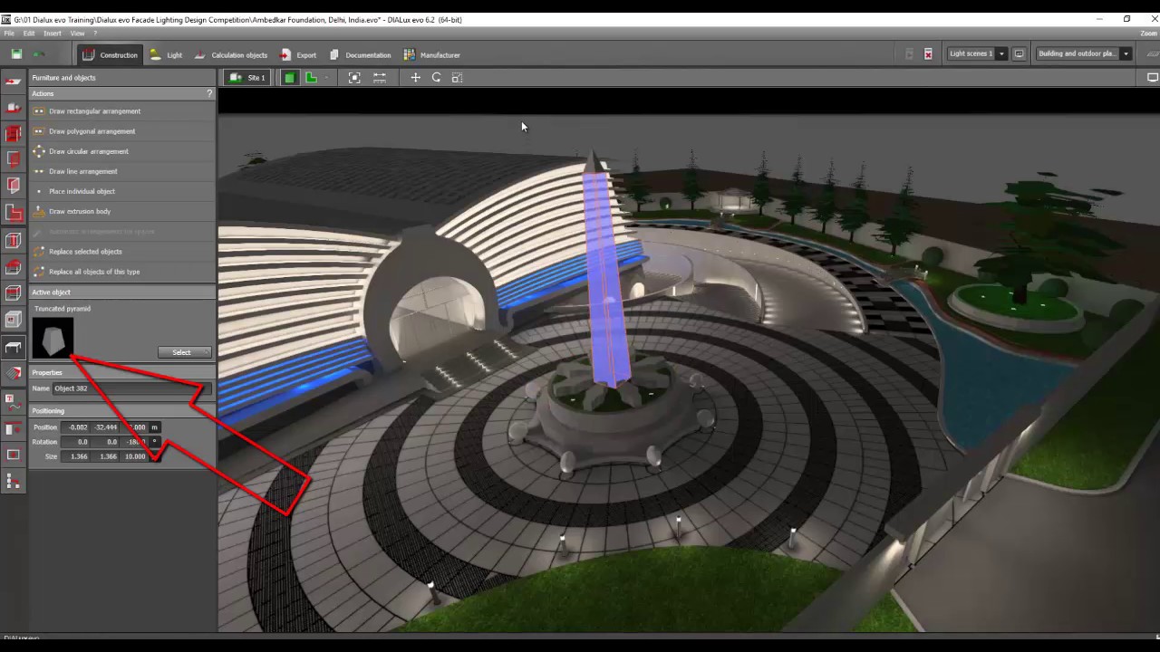
Day 2 Dialux evo Training - Facade & Landscape 5
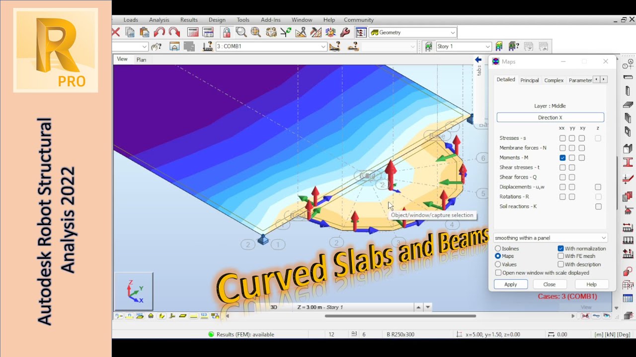
Modeling Circular Beams and Shells in Autodesk Robot: Tips and Techniques
5.0 / 5 (0 votes)
