Industrial Electronics N3 - Silicon Controlled Rectifier (SCR)
Summary
TLDRThis educational video script delves into the Silicon-Controlled Rectifier (SCR), a crucial component in industrial electronics for high voltage and current applications. It explains the SCR's advantages, such as low on-resistance and high resistance, and its applications in electrical machines, power supplies, and car ignition systems. The script covers the SCR's construction from two transistors, its operation with a gate signal, and methods to turn it on and off. It also discusses SCR characteristics, transient suppression techniques, and various control methods including static switching, phase control, and cyclotronic control, providing a comprehensive understanding of this electronic device.
Takeaways
- 😀 Silicon Controlled Rectifiers (SCRs) are used in applications requiring high voltages and high currents.
- 🔌 Like diodes, SCRs allow current to flow in one direction, but they have advantages such as low on-resistance, high forward resistance, low control power, and long life.
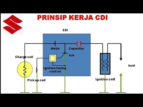
- 🏗️ SCRs are utilized in various applications including electrical machines, relay controls, power supplies, car ignition systems, and light dimmers.
- 🔍 The basic construction of an SCR involves two transistors, specifically a PNP and an NPN transistor, forming three junctions (J1, J2, and J3).
- 🌐 The SCR can be turned on by applying a positive gate voltage, which forward biases J1 and J3, and then forward biases J2 when the gate is triggered.
- 🔄 To switch off an SCR, methods include reducing the anode-cathode current below the minimum holding current or using commutation techniques.
- 🔋 The operation of SCRs involves charging capacitors when they are on, and the SCR remains on as long as the anode-cathode current exceeds the minimum holding current.
- 📈 SCR characteristics resemble those of diodes, conducting when forward biased and blocking when reverse biased, with a small leakage current in the reverse direction.
- 🛠️ Transients, or unwanted voltages and currents, can be mitigated using LC filters, Zener diodes, and Varistors.
- 🔄 Control methods for SCRs include static switching, phase control, cycle control, and cyclotronic control, which combine phase and cycle control techniques.
Q & A
What is a Silicon-Controlled Rectifier (SCR) and why is it used in high voltage and high current applications?
-A Silicon-Controlled Rectifier (SCR) is a semiconductor device that allows current to flow in one direction, similar to a diode. It is used in high voltage and high current applications due to its low on-resistance, high voltage resistance, low control power, and long life.
What are the advantages of using an SCR over diodes and transistors in certain applications?
-The advantages of an SCR include low on-resistance, which allows for higher current flow, and the ability to handle high voltages and currents, making it suitable for applications that require these characteristics.
What are some common applications of SCRs?
-SCRs are used in various applications such as electrical machines, relay controls, power supplies, car ignition systems, and lamp dimmers.
How is an SCR constructed in terms of its basic components?
-An SCR is constructed from two transistors, specifically a PNP transistor and an NPN transistor, which together form three junctions labeled J1, J2, and J3.
How does the SCR conduct current when it is forward-biased?
-When the SCR is forward-biased, junctions J1 and J3 are forward-biased, and J2 is reverse-biased. The SCR will only conduct current when a positive voltage is applied to the gate, causing J2 to also become forward-biased and allowing the current to flow.
What are the methods used to switch an SCR on?
-SCRs can be switched on by applying a positive gate voltage, applying a positive gate current, or by increasing the anode-cathode voltage to reach the breakover voltage.
How is an SCR turned off once it is on?
-An SCR can be turned off by reducing the anode-cathode current below the minimum holding current. This is the minimum current required to keep the SCR in its conducting state.
What is meant by 'breakover voltage' in the context of SCR operation?
-The breakover voltage refers to the point at which the anode-cathode voltage is increased enough to turn on the SCR, even without a gate signal, once it has been reached.
How can a switch be used to control an SCR in a circuit?
-A switch can be connected in series with the SCR to control its state. When the switch is open, the SCR is off, and when the switch is closed, the SCR is on.
What are the different control methods for SCRs mentioned in the script?
-The script mentions static switching, phase control, cycle control, and cyclotronic control as different methods for controlling SCRs.
What is the purpose of LC filters, Zener diodes, and Varistors in relation to SCRs?
-LC filters, Zener diodes, and Varistors are used to eliminate transients, which are unwanted voltages and currents that can occur during the operation of SCRs.
Outlines
🔌 Introduction to Silicon-Controlled Rectifiers (SCRs)
The video script begins with an introduction to industrial electronics, specifically focusing on Silicon-Controlled Rectifiers (SCRs). The speaker, Munya, from Middlebury Campus, explains that SCRs are used in high voltage and high current applications, functioning similarly to diodes by allowing current to flow in one direction. Advantages of SCRs include low on-resistance, high voltage resistance, low control power, and long life. Applications of SCRs are vast, including electrical machines, relay controls, power supplies, car ignition systems, and lamp dimmers. The basic construction of an SCR is also discussed, highlighting its formation by two transistors, a PNP and an NPN, creating three junctions (J1, J2, and J3). The script explains the forward and reverse biasing conditions for these junctions and how the SCR is turned on by applying a positive voltage to the gate, which overcomes the reverse bias of J2.
🛠 Methods to Turn Off SCRs and Their Characteristics
This paragraph delves into the methods of turning off an SCR, which includes reducing the anode-to-cathode current below the minimum holding current. The holding current is defined as the minimum current required to maintain the SCR in its conducting state. The script mentions two primary methods to turn off an SCR: commutation and reducing current below the minimum holding current. Additionally, it describes the use of switches in series or parallel to control the SCR's state. The characteristics of an SCR are compared to those of a diode, emphasizing the SCR's unidirectional conduction and its behavior in both forward and reverse bias conditions. The summary also touches on the gate's role in maintaining the SCR's on-state even after the gate voltage is removed.
🛑 Control and Elimination of Transients in SCR Circuits
The third paragraph discusses the control methods for SCRs, including static switching, phase control, cycle control, and cyclotronic control. It explains the concept of transients as temporary short-duration changes in voltage and current values, which are often unwanted. To mitigate these transients, the script mentions the use of LC filters, Zener diodes, and varistors. It also describes the operation of static switching, which is akin to a half-wave rectifier, and how SCRs conduct during the positive half cycle and not during the negative half cycle. The waveforms for the input voltage and the output after SCR are provided to illustrate this behavior.
🔄 Advanced SCR Control Techniques: Phase and Cycle Control
The final paragraph of the script introduces advanced control techniques for SCRs, such as phase control and cyclotronic control. Phase control is explained with the use of a timer to regulate the SCR's on and off states during the positive half cycle of the input waveform. Full-wave control is also discussed, where the load's connection affects the DC voltage output. The script further explains cycle control, which uses a specific number of cycles to switch the SCR on and off. Lastly, cyclotronic control is described as a combination of phase and cycle control, utilizing both a timer and cycle count to manage the SCR's operation.
Mindmap
Keywords
💡Silicon Controlled Rectifier (SCR)
💡Diode
💡Transistor
💡Junction
💡Gate
💡Forward Bias
💡Reverse Bias
💡Holding Current
💡Commutation
💡Transient
💡Control Methods
Highlights
Introduction to Silicon-Controlled Rectifiers (SCRs) as a replacement for diodes and transistors in high voltage and high current applications.
Explanation of the unidirectional current flow characteristic of SCRs, similar to diodes.
Advantages of SCRs including low on-resistance, high voltage resistance, low control power, and long life.
Applications of SCRs in electrical machines, relay controls, power supplies, car ignition, and lamp dimmers.
Basic construction of an SCR composed of a PNP and NPN transistor, forming three junctions J1, J2, and J3.
Operation of SCRs with conditions for forward and reverse biasing of the internal transistors.
Turning on an SCR by applying a positive gate voltage, which forward biases J2 and activates the device.
Latching behavior of SCRs where once turned on, the gate loses control, and the device remains on even after gate voltage is removed.
Methods to turn off an SCR, including reducing anode-cathode current below the minimum holding current.
Use of switches in series and parallel to control the on/off state of an SCR.
Commutation method to turn off an SCR by applying a reverse voltage.
Characteristic curves of SCRs, comparing them to diodes and explaining their conduction behavior.
Transients in electrical circuits defined as temporary changes in voltage and current values.
Use of LC filters, Zener diodes, and Varistors to eliminate unwanted transients.
Control methods for SCRs including static switching, phase control, cycle control, and cyclotronic control.
Explanation of static switching in half-wave and full-wave rectifiers and their respective waveforms.
Phase control using timers to regulate the conduction period of SCRs.
Cycle control using a specific number of cycles to switch SCRs on and off.
Cyclotronic control combining phase and cycle control methods for SCR operation.
Transcripts
[Music]
good day all
my name is munya am from middlebury
campus
today we'll be looking at industrial
electronics entry
chapter 6 scr which is silicon
controlled
rectifier when diodes and transistors
are failing
they use scr in other words
it means when they need high voltages
and high currents
they use scr
remember in a diode current flows in one
direction
so in scr current also flows
in one direction scr also allows current
to flow in one direction
so for the advantages of scr it has low
on resistance high of resistance
low control power and long life remember
as i said
when they need high voltages and high
currents they use
as they are so obviously when it has low
on resistance it means
it has a higher current
so for the application of scr scr it is
used in electrical machines
and then applications such as relay
controls power supplies
car ignition and then lymph dimmers
and then for the basic construction of
scr
and scr it is formed by
two transistors so it is iron
it is formed by pnp transistor and
npn transistor remember a transistor it
is formed by
two diodes and then in scr
it is formed by two transistors
so in scr it has three junctions
which is j1 j2 and
j3 and then this is a simple office they
are
annoyed which is positive cathode
reaches
negative and then it has a gate
so the second it is forward biased when
j1 is forward biased
j3 is forward bias and j2 it is reversed
buys
and then the second it is reverse biased
when j1
is reverse buys j3 is reverse bias
and then j2 it's forward bias so the
second
even when it is forward but remember i
said when it is forward bias only j1
and j3 they are forward biased
and then j2 it does reverse by so when
the second even if it's forward biased
the second is not gonna be on so you can
only turn on the second
by applying a positive to the gate when
the positive is applied to the gate j2
will also be forward biased and then the
second it's gonna be
on
and then method used to switch the scr
on
we have applying a positive gate
applying a positive gate current and
then by increasing the android cathode
voltage to such an extended
the break over voltage is reached
so in other words when they say by
applying
a positive gate current remember i
said for a forward bias j1 and j3 they
are reversed by
zen then j2 it is four was biased and
then the second will only be on when the
positive is
applied to the gate then j2 will be
forward but
then the second is on and then when they
say by applying a positive gate current
they mean by applying a positive
clock to the gate then the circuit will
be on
j2 will be forward by the then the
second will be on is the one that i was
talking about
and then for by increasing the unknown
trick effect
which is a break over voltage turn on
so for this one when you apply more
positive to the anode the second will be
on so when the second it's on
even when you remove the positive
from the gate the circuit is not going
to be off
once the circuit is on the gate will
lose control and
indicate when it loses control even when
you remove the positive from the gate
the circuit will still be on
so we use the following methods
to turn off the scr
reduction of android cathode current
below the minimum
holding current a holding current is
defined is
minimum current required to hold the scr
in its conducting state
so by reducing a current
below minimum holding current is the
method that we use to turn off the
sdr circuit we have two methods remember
is commutation and by reducing current
to
below the minimum holding current so
when you connect a switch in series with
the scr
the second is gonna be off remember when
the switch is open
the second is gonna be off and then when
the switch is closed the circuit will be
on
and then again you can turn off the
circuit by applying
a switch in parallel to the scr
when the switch is in parallel with the
scr the second is gonna be
off when the switch is open and then
again by connecting a transistor
in parallel to the scr the circuit is
gonna be
off and then for commutation method
accommodation method
the scr is going to be off by applying
a positive battery today
i mean by applying a reversal bedroom to
the svr
when a reversal battery is applied to
the sdr
the second is gonna be it's gonna be off
reversal battery it means remember this
is a node which is the positive this is
calculated which is the negative
when positive is applied to the negative
and the negative is applied to the
positive the second this penalty is
going to be
off
and then let's check the second
for the operation of the circuit when
scr is connected
for this one it represents more
practical seconds of
scr and then for this one
switch one it's open
the sdr is gonna be off and then when
switch
one is closed the scr will be on and
then when the scr
is on the capacitor i will charge and
then when you check
s2 s2 is connected to the ground so when
you close
s2 the second is gonna be
off because
s2 is connected to the ground so it
means annoyed
it's
it's made negative with respect to the
half point
then the second is gonna be off switch
one when is closed scr is gonna be on
and then the capacitor will charge when
search two
is closed the second is gonna be off
because the anode is made negative
within respect to the cathode
and then scr characteristics
this one is the same as the
characteristic curve of
a diode remember for a diode the current
will conduct 20 days forward biased and
will not conduct when it is
reversed biased
when it is forward burst
i mean when it is reversed but it's only
a small leakage current flows in the
reverse direction
when it deserves spices only a small
leakage current will flow
in the reverse direction it means when
it is reversed by that means j1
and j3 they are forward by then j2 it
deserves spice
so it means the circuit will not conduct
until you
apply a positive to the gate
and then in the forward direction when
no gate has been applied to a small
leakage
it's more leakage current also flows is
the one that i was talking about the
circuit will conduct
in forward biased when a positive is
applied to
the gate when
gate current is applied the scr conducts
and then the scr will remain on for as
long as the android should cathode
current exit
the minimum holding current so the
second is going to be
on even when you remove the positive
from the gate the circuit will still be
on because
the gate loses control
so in other ways it means the scr will
only conduct when it is
forward biased and then when it is
reversed by the scr will
not conduct
for a transient they saying a transit
can be
defined as a temporary short duration
during which known voltage
and current values change from existing
values to new values
in other words they mean
a transient it's we can say transients
they are unwanted voltages and unwanted
currents
as we can simply say they are unwanted
voltages and unwanted
currents so in order to eliminate
the unwanted voltages
we use lc filters zener tires and
varistas so you must be able to explain
numerous knowledge along methods that
they are used to eliminate transients
and then for control methods of scr
we have static switching phase control
and then cycle control and cycle
trony control so for static switching
for static switching is the same as the
half wave rectifier
so for the operation of the circuit
you'll have positive then you'll have
negative
so during positive half cycle with
positive then it's negative
so jordan positive half cycle
the scr will be on when the switch is
closed the sdr will be on
and then during negative half cycle
remember after i cycle the polarity
changes it means during negative half
cycle
you'll have positive you'll have
negative
so in a second current flows from
positive to negative then the positive
is going to be here
and then when you start from positive
remember and with this positive cathode
it's negative when you start from
positive the scr it is reverse biased
and then when it is reversed by that
means
it will not conduct so during positive
half cycle
is positive is negative you start from
positive this one is positive
it's negative it means it is forward by
then then during positive half cycle
when switch is closed the scr
will conduct and then during negative
half cycle
the scr will not conduct this they are
the waveforms
this is the input voltage for hc this is
the output form
after scr this is the output during
positive half cycle will have a waveform
because
sdr conduct during negative half cycle
scr does not conduct
you'll have a space during positive half
cycle
will conduct you'll have a waveform
negative half cycle will have a space
because it does not conduct
positive half cycle you will have a
waveform cause it
conducts so for a full wave control
for a full wave control the first one
when the load
is increased with the supply it's for
shc voltage and then
when the load is connected in series
with the scr
is for a dc voltage
this is the input waveform for ac and
then
output waveform for dc for
a full wave control
and then for a face control a face
control they use
a timer to control as they are so
for the shaded area is for conduction
and then
unshaded area it's off delay
so they use a timer to control the scr
so of delay it means the timer is off
and then on delay
it means the timer it's on so they use
a timer to switch the scr
on and off
so for a half wave control
they've used a timer to control the
circuit
during positive half cycle the control
circuit
the timer will be on and then when it is
on the scr will also be on
and then during negative half cycle the
polarity changes after a cycle it means
you will have
positive will have negative during
negative half cycle
the sar the timer
the control circuit will not be on then
we have a space shuttle positive half
cycle is positive it's negative
and then when the control circuit is on
the scr will be on then we'll have a
waveform and then for a full wave
control
during positive half cycle we have
positive we have negative
so during positive half cycle control
circuit one
will be on and then when it is on will
turn on
scr1 during negative half cycle
we have positive we have negative
only scr2
will be on the control circuit two will
be on
and then as the r2 will be on
and then for cycle control
for a second control they use number of
cycle
to switch on scr
to switch scr on and off so it
means when they've used eight cycle to
switch on the essay are they gonna use
another eight cycle to switch off scr so
they use
number of cycle to switch as they are on
and
off for cyclotronic control
cyclotronic control is the combination
of phase control and cycle control
in other ways it means they've used a
timer and number of
cycle to turn on that second
[Music]
you
関連動画をさらに表示
How to use MOSFET as a Switch ? MOSFET as a Switch Explained
3 point starter | 3 point starter dc motor | three point starter of dc motor | three point starter
Dasar Elektronika ; Dioda Sebagai Saklar
speed control of dc motor | speed control of dc shunt motor | dc motor speed control | series motor
What is Field Effect Transistor (FET)? || Differences between BJT and FET || Types of FET
Device Physics II
5.0 / 5 (0 votes)