Sistem Mikrokontroler - 09 - Analog to Digital Converter (ADC)
Summary
TLDRThis video explains the fundamentals of Analog-to-Digital Converters (ADC) in microcontrollers, with a focus on the Atmega16. It covers how ADCs convert analog signals, such as voltage or sensor inputs, into digital data for processing. Key concepts like resolution, reference voltage, and digital output calculation are clearly described. The video also details the Atmega16 ADC architecture, including channels, registers (ADMUX, ADCSRA, ADCL/ADCH), and the process of starting, monitoring, and reading conversions. Practical examples of initialization and conversion in C programming are provided, making it a comprehensive guide for beginners learning to interface analog signals with microcontrollers.
Takeaways
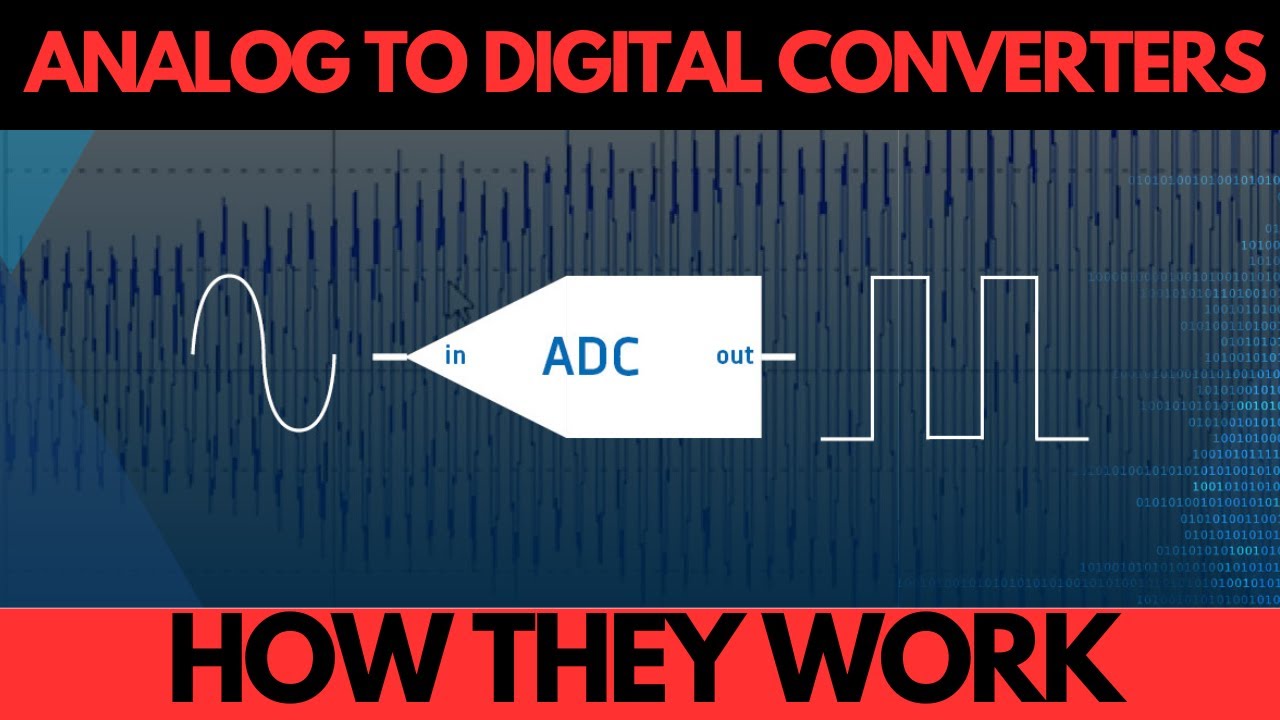
- 😀 ADC (Analog-to-Digital Converter) converts analog signals (e.g., voltage) into digital signals that can be processed by microcontrollers.
- 😀 The range of analog inputs to an ADC (like 0-5V) is mapped into a corresponding digital output (e.g., 0-255 in an 8-bit system).
- 😀 ADC resolution refers to the smallest change in input voltage that can be detected. It is inversely proportional to the bit-depth of the ADC.
- 😀 Formula for ADC resolution: Resolution = (Voltage Range) / (2^n), where 'n' is the bit-depth of the ADC.
- 😀 The formula for calculating the digital output of an ADC conversion is: D_out = (Analog Input / Reference Voltage) * (2^n - 1).
- 😀 Example: For an 8-bit ADC with a 5V reference, an input of 2.5V results in a digital output of 127.
- 😀 ATmega16 microcontroller has an 8-channel ADC, capable of multiplexing between input channels (ADC0 to ADC7).
- 😀 Multiplexing allows one ADC to sample multiple analog inputs by selecting one channel at a time.
- 😀 The conversion process in ADC involves selecting an input, converting it, and then storing the result in an ADC data register.
- 😀 Important ADC control registers in ATmega16 include the ADC Multiplexer Section Register, ADC Control and Status Register, and ADC Data Register.
- 😀 To start ADC conversion, set the 'start conversion' bit in the control register. After conversion, the result can be read from the data register.
Q & A
What is an Analog-to-Digital Converter (ADC)?
-An Analog-to-Digital Converter (ADC) is a system that converts an analog signal (like voltage) into a digital signal. This conversion allows analog information to be processed by digital systems like microcontrollers.
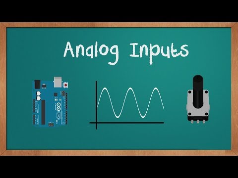
What is the difference between analog and digital signals?
-Analog signals can take on any value within a given range and change continuously, while digital signals are discrete and represented in binary (0s and 1s).
How does an ADC work?
-An ADC works by sampling an analog signal, comparing it against a reference voltage, and then converting the analog value into a corresponding digital value, typically represented by a binary number.
What is the resolution of an ADC?
-The resolution of an ADC refers to the smallest detectable change in the input signal. It is determined by the number of bits in the ADC (e.g., an 8-bit ADC can detect 256 levels).
How do you calculate the resolution of an ADC?
-The resolution of an ADC is calculated using the formula: Resolution = (V_max - V_min) / 2^n, where V_max and V_min are the reference voltage range, and n is the number of bits in the ADC.
What is the output of an ADC?
-The output of an ADC is a digital value that corresponds to the input analog signal after conversion. For instance, if the input is 2.5V and the reference is 5V with an 8-bit ADC, the output is 127.
What is the reference voltage in an ADC?
-The reference voltage is the voltage range that the ADC uses to convert the analog signal. It can be set to a value like Vcc, Aref, or an internal 2.5V reference, and it affects the conversion accuracy.
What are the important registers in an ADC system?
-Important registers include the ADC multiplexer register (to select the input channel), ADC control and status register (to enable the ADC and start conversion), and the ADC data register (to store the converted value).
How does the Atmega16 microcontroller handle ADC conversion?
-The Atmega16 microcontroller has an 8-channel ADC, with a multiplexed input, meaning only one channel is converted at a time. The conversion result is stored in an 8-bit or 10-bit data register.
What is the purpose of the prescaler in ADC conversion?
-The prescaler determines the clock speed for the ADC conversion process. It divides the system clock by a factor (e.g., 2, 4, 8) to control the ADC's conversion rate and timing.
Outlines

このセクションは有料ユーザー限定です。 アクセスするには、アップグレードをお願いします。
今すぐアップグレードMindmap

このセクションは有料ユーザー限定です。 アクセスするには、アップグレードをお願いします。
今すぐアップグレードKeywords

このセクションは有料ユーザー限定です。 アクセスするには、アップグレードをお願いします。
今すぐアップグレードHighlights

このセクションは有料ユーザー限定です。 アクセスするには、アップグレードをお願いします。
今すぐアップグレードTranscripts

このセクションは有料ユーザー限定です。 アクセスするには、アップグレードをお願いします。
今すぐアップグレード関連動画をさらに表示


5.0 / 5 (0 votes)
