BJT- Common Base Amplifier Explained
Summary
TLDRIn this video, we explore the common base amplifier in electronics, building on previous lessons about BJT amplifiers. The video walks through the basic circuit setup, explaining how the AC input signal is applied and how biasing is achieved. It covers key amplifier characteristics, including voltage gain, input impedance, and output impedance, with detailed small-signal analysis. The video also discusses the effect of resistors on voltage gain and provides insights on improving performance with bypass capacitors. Finally, the common base amplifier's application in impedance matching for high-frequency transmission lines is highlighted.
Takeaways
- 😀 The Common Base Amplifier (CBA) is a type of transistor amplifier where the base terminal is common to both the input and output sides of the circuit.
- 😀 In the common base amplifier, the input signal is applied at the emitter terminal, and the output is measured at the collector terminal.
- 😀 The base terminal is treated as AC ground in this configuration due to DC biasing voltage applied at the base.
- 😀 Coupling capacitors are used to isolate AC and DC signals, but they require a proper path for DC biasing current to work effectively.
- 😀 The base of the transistor can be biased using a fixed voltage via a base resistor, or using a voltage divider for biasing.
- 😀 The voltage gain (Vo/Vin) of the common base amplifier is influenced by factors like the collector resistor (Rc), the input resistance (Rπ), and the base resistor (Rb).
- 😀 The voltage gain formula of the common base amplifier can be simplified to Rc / (1/gm + Rb/β), where gm is the transconductance and β is the current gain.
- 😀 The output impedance of the common base amplifier is equal to the collector resistor (Rc), as seen from the output side.
- 😀 The input impedance of the common base amplifier is typically low and can be calculated as the parallel combination of emitter resistor (Re) and (1/gm + Rb/β).
- 😀 A bypass capacitor can be used to improve the voltage gain by reducing the effect of the base resistor Rb on the input impedance and voltage gain.
- 😀 Common base amplifiers are useful for impedance matching, particularly at high frequencies, where they can interface with low-impedance transmission lines.
Q & A
What is the primary focus of the video?
-The primary focus of the video is to explain the common base amplifier, its characteristics, and how it functions in comparison to other BJTs like the common-emitter and common-collector amplifiers.
Why is the amplifier called 'common base'?
-The amplifier is called 'common base' because the base terminal is common to both the input and output sides of the circuit, with the input signal applied to the emitter and the output taken from the collector.
What happens when a coupling capacitor is used incorrectly in the common base amplifier circuit?
-If a coupling capacitor is used incorrectly, it can act as an open circuit for DC signals, preventing the bias current from flowing. This results in no output signal. To solve this, a series resistor is required to properly couple the input signal to the emitter.
How is the base terminal of the common base amplifier typically biased?
-The base terminal is typically biased with a fixed DC voltage through a base resistor or via a voltage divider bias, allowing the circuit to operate correctly under AC signal conditions.
What is the small-signal equivalent circuit used for?
-The small-signal equivalent circuit is used for analyzing the amplifier's characteristics, including voltage gain, input impedance, and output impedance, by replacing the transistor with its small-signal model and simplifying the circuit.
How is the voltage gain of the common base amplifier derived?
-The voltage gain is derived by considering the output voltage in terms of the collector current, then expressing the input voltage (Vπ) in terms of the input signal. The final expression for voltage gain is given by Rc / {(1/gm) + (Rb/β)}.
What factors affect the voltage gain in a common base amplifier?
-The voltage gain is influenced by the collector resistor (Rc), the base resistor (Rb), and the transconductance (gm). A base resistor will reduce the voltage gain, and its effect can be minimized by using a bypass capacitor or adjusting the design.
What is the output impedance of a common base amplifier?
-The output impedance of a common base amplifier is equal to the collector resistor (Rc), as seen from the output side after short-circuiting the input voltage source.
Why is the input impedance of the common base amplifier low?
-The input impedance of the common base amplifier is low because it is mainly determined by the transconductance (gm) and emitter resistance (Re), which leads to a low impedance path for the input signal.
What practical application does a low input impedance common base amplifier have?
-A low input impedance common base amplifier is useful for impedance matching, particularly in high-frequency applications like transmission lines, where the characteristic impedance is in the range of tens of ohms.
Outlines

このセクションは有料ユーザー限定です。 アクセスするには、アップグレードをお願いします。
今すぐアップグレードMindmap

このセクションは有料ユーザー限定です。 アクセスするには、アップグレードをお願いします。
今すぐアップグレードKeywords

このセクションは有料ユーザー限定です。 アクセスするには、アップグレードをお願いします。
今すぐアップグレードHighlights

このセクションは有料ユーザー限定です。 アクセスするには、アップグレードをお願いします。
今すぐアップグレードTranscripts

このセクションは有料ユーザー限定です。 アクセスするには、アップグレードをお願いします。
今すぐアップグレード関連動画をさらに表示

Op-Amp: Summing Amplifier (Inverting and Non-Inverting Summing Amplifiers)

BJT Class A Amplifiers

COME REGOLARE L'AMPLIFICATORE per CHITARRA, settaggi equalizzazione, come funziona | Tutorial
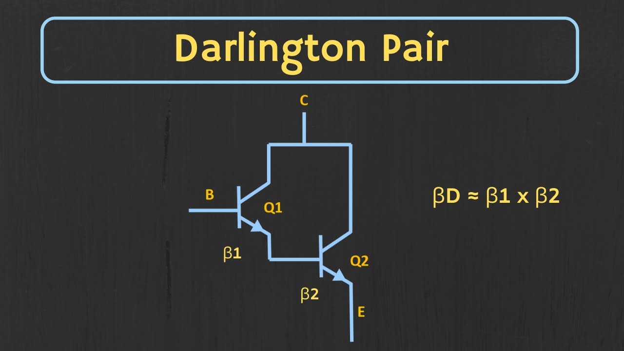
Darlington Pair Explained | The Darlington Pair as a Switch

Reading an Unknown Number of Inputs in C++

Instrumentation Amplifier Explained (with Derivation)
5.0 / 5 (0 votes)
