transformers for IGCSE Physics, GCE O level Physics
Summary
TLDRThis script explores the concept of mutual induction in transformers, explaining how an electromagnet induces an EMF in a second solenoid. It delves into the workings of transformers, distinguishing between step-up and step-down types, and their crucial role in the National Grid to minimize energy loss through high voltage transmission. The script also highlights the inefficiency of transformers with DC and the importance of AC in power transmission, concluding with a demonstration of power loss calculations in cables at different voltages.
Takeaways
- 🧲 Mutual Induction: When an electromagnet is switched on or off, a momentary EMF is induced in a nearby solenoid due to the changing magnetic field.
- 🔧 Steady Current No EMF: A steady current through an electromagnet does not induce EMF in a secondary solenoid because the magnetic field remains constant.
- 🔄 Alternating Current Effect: Using an alternating power supply results in an alternating magnetic field that induces an alternating EMF in the secondary solenoid.
- 🔗 Increasing Induced EMF: The induced EMF in the secondary solenoid can be increased by adding more turns to the coil or using an iron core that extends through the secondary solenoid.
- 🌐 Principle of Transformers: Transformers operate on the principle of mutual inductance to transfer electrical energy efficiently between two coils.
- ⚙️ Components of a Transformer: A basic transformer consists of an AC input power supply, a primary coil, an iron core, and a secondary coil.
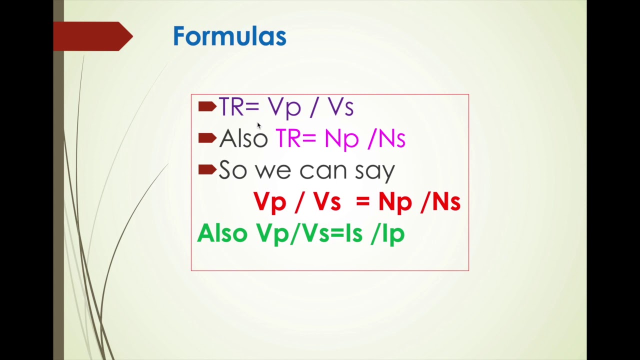
- ⏫⏬ Types of Transformers: There are step-up transformers that increase voltage and step-down transformers that decrease voltage, differentiated by the number of turns on their coils.
- 🔌 National Grid Application: Transformers are crucial in the National Grid for transmitting electricity at high voltages and low currents to minimize energy loss.
- ⚡ High Voltage Dangers: High voltage transmission requires safety measures such as elevated pylons or underground cables to avoid danger.
- 🔌 AC vs. DC in Transformers: Transformers work with AC currents, which can be easily stepped up or down, unlike DC which does not induce EMF due to its steady magnetic field.
- 📉 Power Loss Calculation: Demonstrates that high voltage transmission reduces power loss in cables, as shown by comparing power losses at different voltages and currents.
Q & A
What is the phenomenon of mutual induction?
-Mutual induction occurs when an electromotive force (EMF) is induced in a secondary solenoid due to the changing magnetic field created by a current in a nearby primary solenoid.
Why is there no EMF induced in the second solenoid with a steady current through the electromagnet?
-No EMF is induced in the second solenoid with a steady current because the magnetic field is not changing; mutual induction requires a varying magnetic field.
What happens when an alternating power supply is used instead of a DC power supply in an electromagnet?
-An alternating power supply creates an alternating magnetic field around the electromagnet, which interacts with the secondary solenoid, inducing an alternating EMF in it.
How can the induced EMF in the second solenoid be increased?
-The induced EMF in the second solenoid can be increased by increasing the number of turns on the secondary solenoid, using an iron core in the electromagnet, or having the iron core go right through the secondary solenoid.
What is a transformer and what is its primary function?
-A transformer is an electrical device used to increase or decrease the voltage of an AC current. It works based on the principle of mutual induction between two coils.
Why are transformers not effective with DC power?
-Transformers are not effective with DC power because DC creates a steady magnetic field that does not interact with the coil to induce an EMF.
What are the two main types of transformers?
-The two main types of transformers are step-up transformers, which increase the voltage of an input power supply, and step-down transformers, which decrease the voltage.
How do transformers help reduce energy loss in the National Grid?
-Transformers help reduce energy loss by allowing electricity to be transmitted at high voltages and low currents, which minimizes the amount of energy lost as heat in the transmission lines.
What is the significance of using high voltage transmission lines for long-distance electricity transmission?
-High voltage transmission lines are used to minimize energy loss during long-distance transmission. By increasing the voltage and reducing the current, thinner, lighter, and cheaper cables can be used.
Why is alternating current preferred for electricity transmission over long distances?
-Alternating current is preferred for long-distance transmission because it can be easily stepped up and down in voltage using transformers, which helps in minimizing power loss and efficiently transmitting electricity.
How does the power loss in a cable relate to the current flowing through it?
-The power loss in a cable is directly proportional to the square of the current flowing through it (as per the formula Power Loss = Current^2 * Resistance). Therefore, reducing the current for the same power transmission reduces the power loss.
Outlines

このセクションは有料ユーザー限定です。 アクセスするには、アップグレードをお願いします。
今すぐアップグレードMindmap

このセクションは有料ユーザー限定です。 アクセスするには、アップグレードをお願いします。
今すぐアップグレードKeywords

このセクションは有料ユーザー限定です。 アクセスするには、アップグレードをお願いします。
今すぐアップグレードHighlights

このセクションは有料ユーザー限定です。 アクセスするには、アップグレードをお願いします。
今すぐアップグレードTranscripts

このセクションは有料ユーザー限定です。 アクセスするには、アップグレードをお願いします。
今すぐアップグレード関連動画をさらに表示
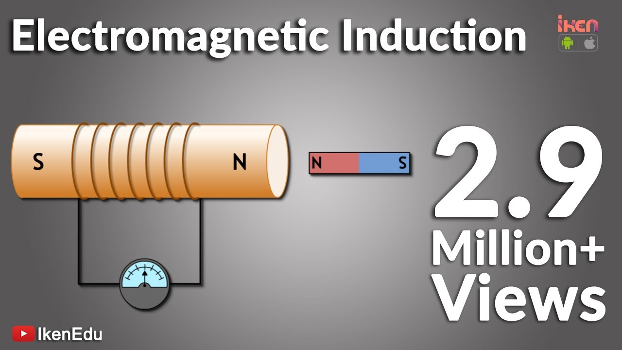
What is Electromagnetic Induction? | Faraday's Laws and Lenz Law | iKen | iKen Edu | iKen App
Materi Kemagnetan Kelas 9 (Part-5) Induksi Elektromagnetik
GGL ( GAYA GERAK LISTRIK ) PADA KAWAT LURUS

Understanding Inductors!
Materi Kuliah Transformer #1

AC Generator 3D animation | Electromagnetic Induction | Electric generator | Working of AC Generator
5.0 / 5 (0 votes)
