DASAR PEMOGRAMAN PLC - SIMBOL - SIMBOL DASAR PLC
Summary
TLDRThis tutorial introduces the basics of PLC (Programmable Logic Controller) programming, focusing on ladder diagrams. It explains key PLC symbols, including normally open (Ndut) and normally closed (NC) inputs, as well as series and parallel connections. The video covers how to combine these symbols to form logical sequences that control outputs. It provides an easy-to-understand breakdown of how these components work together in PLC programming, aiming to help beginners understand the foundational concepts and apply them in real-world scenarios.
Takeaways
- 😀 A Ladder Diagram (LD) in PLC programming resembles a ladder, with inputs on the left and outputs on the right.
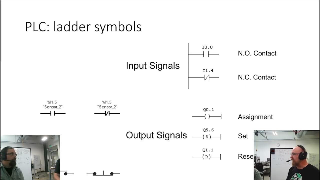
- 😀 The symbol 'LUT' represents a Normally Open (NO) input contact, which is open by default and closes when energized.
- 😀 The symbol 'LDR' represents a Normally Closed (NC) input contact, which is closed by default and opens when energized.
- 😀 Inputs can be connected in series or parallel to create different logical conditions for outputs.
- 😀 In series connections, all contacts must be closed for current to flow, while in parallel, any closed contact will allow current to flow.
- 😀 Output coils are placed at the far right of a Ladder Diagram and activate when the conditions from the inputs are met.
- 😀 Combining input contacts (NO or NC) in series or parallel creates logical conditions that determine the behavior of outputs in the PLC program.
- 😀 Ladder Diagrams are similar to electrical wiring diagrams, with clear visual representation of how inputs and outputs are connected.
- 😀 Understanding the basic symbols like NO, NC, and output coils is essential for designing effective PLC programs.
- 😀 Practical use of these symbols in a Ladder Diagram allows for controlling machines or processes by defining logical conditions for each output.
- 😀 The tutorial emphasizes the importance of mastering these basic symbols as the foundation for more advanced PLC programming.
Q & A
What is the purpose of a PLC ladder diagram?
-The purpose of a PLC ladder diagram is to represent the logic of a PLC program visually, using symbols that resemble a ladder, which simplifies the understanding and programming of industrial control systems.
Why is it called a 'ladder diagram'?
-It is called a 'ladder diagram' because its structure resembles a ladder, with two vertical rails and horizontal rungs representing the various control processes and logic operations.
What does the 'Ndut' or 'LCD Duh' symbol represent in a ladder diagram?
-'Ndut' or 'LCD Duh' refers to a basic input symbol, specifically a Normally Open (NO) contact. This symbol represents an input that is in an open state when the PLC is not activated.
What is the difference between a Normally Open (NO) and a Normally Closed (NC) contact in ladder diagrams?
-A Normally Open (NO) contact, symbolized as 'NO', is open by default and closes when activated, while a Normally Closed (NC) contact, symbolized as 'NC', is closed by default and opens when activated.
What does it mean when two NO contacts are connected in series?
-When two Normally Open (NO) contacts are connected in series, it means that both contacts must be activated in order to complete the circuit and trigger the associated output.
What happens when contacts are connected in parallel in a PLC ladder diagram?
-When contacts are connected in parallel, the circuit will complete if any of the contacts in the parallel arrangement are activated, allowing for multiple conditions to trigger the same output.
How is an output symbol represented in a ladder diagram?
-An output symbol in a ladder diagram is usually represented on the far right, and it indicates the action or result that occurs when all the necessary conditions from the inputs are met.
What does the term 'PLC program' refer to in this context?
-A PLC program refers to the set of instructions written to control industrial processes. The program is often depicted in ladder diagram format, which represents the logic and sequence of operations.
What is the significance of the output address in a PLC ladder diagram?
-The output address in a PLC ladder diagram specifies the location or identifier of the output device that will be activated when the logic conditions are satisfied. For example, '0.00' or '1.000' indicate specific outputs.
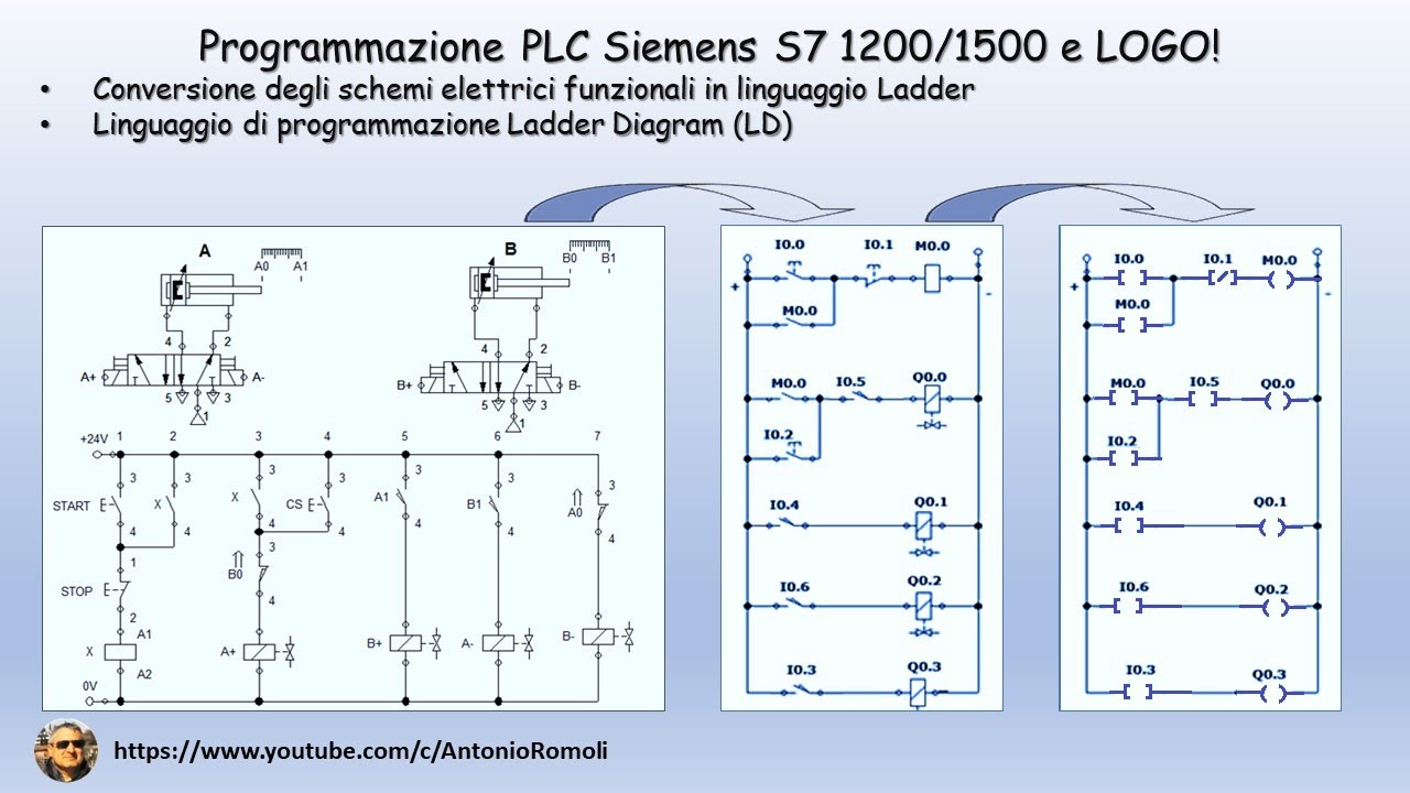
How do ladder diagrams relate to wiring diagrams in industrial control systems?
-Ladder diagrams are conceptually similar to wiring diagrams in that they both represent the connections and logic of a control system. However, ladder diagrams are used for programming PLCs, while wiring diagrams focus on physical electrical connections.
Outlines

このセクションは有料ユーザー限定です。 アクセスするには、アップグレードをお願いします。
今すぐアップグレードMindmap

このセクションは有料ユーザー限定です。 アクセスするには、アップグレードをお願いします。
今すぐアップグレードKeywords

このセクションは有料ユーザー限定です。 アクセスするには、アップグレードをお願いします。
今すぐアップグレードHighlights

このセクションは有料ユーザー限定です。 アクセスするには、アップグレードをお願いします。
今すぐアップグレードTranscripts

このセクションは有料ユーザー限定です。 アクセスするには、アップグレードをお願いします。
今すぐアップグレード関連動画をさらに表示

Example PLC: EATON EASY Intelligent Relay (Full Lecture)

Ladder Logic Diagrams for PLCs | Industrial Automation
PLC: convertire lo schema elettrico funzionale in linguaggio di programmazione Ladder (Video 1.1)
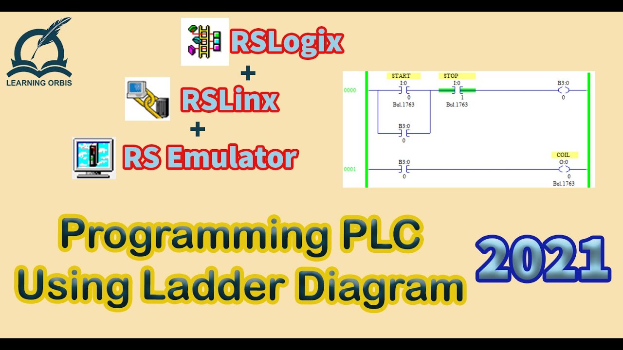
How to Program PLC Using Ladder Diagram | RSLogix

BELAJAR LADDER PROGRAM PLC DARI NOL | EPISODE 1 | GERBANG LOGIKA AND
SysAp 7 1 Ladder Logic
5.0 / 5 (0 votes)
