Modellierung von Datenbanken - Erstellung eines ERM
Summary
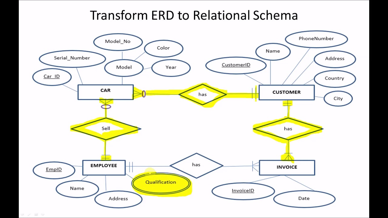
TLDRThis video provides a detailed guide on how to convert an Entity-Relationship (ER) diagram to a relational schema in database design. It covers key concepts such as converting relationships, assigning foreign keys, handling one-to-many and many-to-many relationships, and the steps involved in transforming ER diagrams. Key steps include adding foreign keys, transforming many-to-many relationships into additional entities, and incorporating relevant attributes. The process concludes with completing the ER diagram by applying these transformation rules. The tutorial is designed to assist in mastering these concepts through practical application.
Takeaways
- 😀 Define entities and relationships clearly in an entity-relationship diagram (ERD) to capture data accurately.
- 😀 Focus on understanding entity attributes and how they are represented as fields in tables.
- 😀 Ensure that primary keys (PK) are uniquely identified for each entity to maintain data integrity.
- 😀 Foreign keys (FK) are used to link entities, and their placement should follow the rules of relationships (e.g., one-to-many or many-to-many).
- 😀 In a one-to-many (1:N) relationship, the foreign key is placed on the 'many' side of the relationship.
- 😀 For many-to-many (N:M) relationships, a new entity is created to resolve the relationship, and foreign keys from both entities are included in this new entity.
- 😀 The relationship itself in N:M relationships becomes an entity, which can have its own attributes and primary key.
- 😀 Be sure to add any extra attributes that are not part of the key but are essential for the business logic of the system.
- 😀 When resolving complex relationships, ensure that you replace the simple diamond (representing a relationship) with a double diamond to indicate a more intricate structure.
- 😀 Throughout the ERD design process, review and adjust relationships, attributes, and foreign keys to ensure the diagram is logical, consistent, and reflects the real-world data structure.
Q & A
What is the first step in creating an Entity-Relationship (ER) diagram?
-The first step is to define the entities. These are the key objects or things that will be represented in the database, such as 'student', 'class', or 'teacher'.
How are relationships between entities represented in an ER diagram?
-Relationships between entities are represented using diamonds. The cardinality of the relationship is noted using numbers, like 1:1, 1:N, or N:M, which indicate how many instances of one entity can be associated with another.
What is meant by cardinality in the context of ER diagrams?
-Cardinality refers to the number of instances that an entity can be associated with another entity. The common cardinalities are one-to-one (1:1), one-to-many (1:N), and many-to-many (N:M).
What is the significance of a 'foreign key' in an ER diagram?
-A foreign key is a field in a table that creates a link between two tables. It ensures referential integrity by linking a row in one table to a row in another table.
What is the rule for placing a foreign key in a 1:N relationship?
-In a 1:N relationship, the foreign key is always placed on the 'many' side of the relationship. This helps to link multiple instances of the 'many' entity to one instance of the 'one' entity.
How is a many-to-many (N:M) relationship handled in ER diagrams?
-A many-to-many (N:M) relationship is resolved by creating a new entity (a relationship entity) that has its own primary key and two foreign keys—one for each side of the original relationship. This entity connects the two entities involved in the N:M relationship.
What is the purpose of the 'double diamond' in ER diagrams?
-The 'double diamond' is used to signify a relationship entity in the diagram, which is created to handle many-to-many relationships. It visually distinguishes the relationship from other entity types.
What additional elements can be added to an ER diagram after the entities and relationships are defined?
-After defining the entities and relationships, additional attributes can be added to the entities. These attributes provide more detailed information about each entity, like a student's name or a class's start date.
Why is it important to follow the 'one-side foreign key rule' in ER diagrams?
-The 'one-side foreign key rule' ensures that the diagram correctly reflects the direction of relationships, helping maintain the integrity and clarity of how entities relate to one another. It simplifies the database design and query structure.
How can the concepts from the script be applied in real-world database design?
-The rules and methods outlined in the script can be applied to any real-world database design process, such as in applications involving user management, product catalogs, or educational systems. The process of defining entities, relationships, and cardinalities helps to structure the database for efficient data storage and retrieval.
Outlines

このセクションは有料ユーザー限定です。 アクセスするには、アップグレードをお願いします。
今すぐアップグレードMindmap

このセクションは有料ユーザー限定です。 アクセスするには、アップグレードをお願いします。
今すぐアップグレードKeywords

このセクションは有料ユーザー限定です。 アクセスするには、アップグレードをお願いします。
今すぐアップグレードHighlights

このセクションは有料ユーザー限定です。 アクセスするには、アップグレードをお願いします。
今すぐアップグレードTranscripts

このセクションは有料ユーザー限定です。 アクセスするには、アップグレードをお願いします。
今すぐアップグレード関連動画をさらに表示


5.0 / 5 (0 votes)
