Annotation

Autodesk
20 Jan 201105:17

Summary

TLDRThis tutorial guides viewers through annotating an AutoCAD drawing with dimensions and text. It demonstrates how to access and modify annotation styles, add various dimensions such as linear, angular, radial, and diameter, and adjust precision. The video also covers adding center marks, continuous dimensions, and multi-line text annotations. Finally, it explains transitioning from model space to paper space for printing or plotting the completed drawing.

Takeaways

  • 📏 Annotation is crucial for completing an AutoCAD drawing, with dimensions and text being key elements.
  • 🔧 Users can access annotation styles through the Annotation dropdown list, where they can view and modify text style and dimension settings.
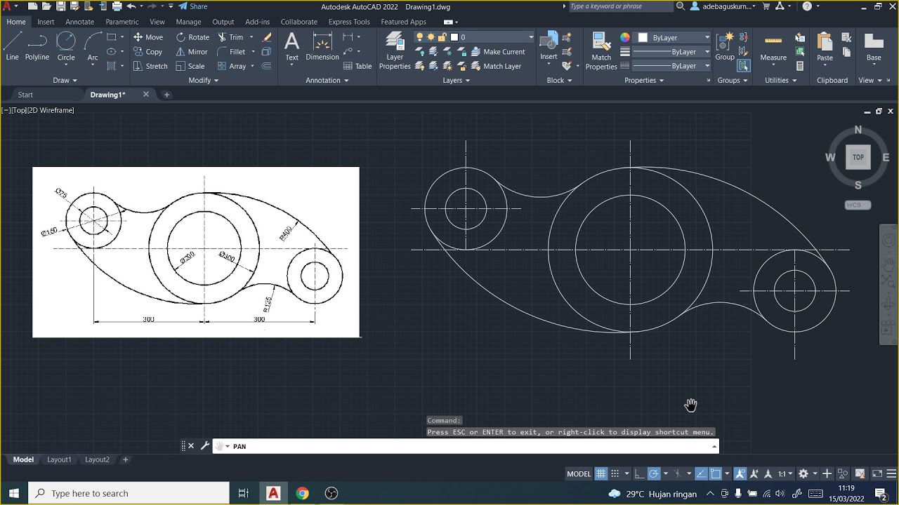
  • 📐 Adding a linear dimension involves selecting endpoints and adjusting precision, such as setting the number of decimal places.
  • ✏️ Dimension style can be modified to change the appearance and precision of dimensions, like setting two decimal places for linear dimensions.
  • 🔼 A tip for placing dimensions is to use the right-click option to select the object directly, streamlining the process.
  • 📐 Angular and radial dimensions can be added to drawings, with center marks being a default feature for radial dimensions.
  • 🔄 To add center marks to other circles, users can access the Center Mark tool from the Annotate tab and modify its appearance in the Dimension Style.
  • 📏 Continuous dimensions can be added to parts of the drawing to show measurements across multiple points.
  • 📄 Switching between model space and paper space is necessary for printing or plotting the drawing, with paper space providing a layout view.
  • 🖨️ To finalize the annotation, multi-line text can be added to provide additional information, such as material type and thickness.
  • 🔙 After adding text, it's important to return to paper space to ensure all elements are visible and correctly positioned for plotting.

Q & A

  • What are two examples of annotation required to complete an AutoCAD drawing?

    -Dimensions and text are two examples of annotation required to complete an AutoCAD drawing.

  • How can you access the annotation styles in AutoCAD?

    -You can access the annotation styles by going to the annotation drop-down list in AutoCAD.

  • What information can be seen under the text style in AutoCAD?

    -Under the text style, you can see the font name, the style, and the height.

  • How can you add a linear dimension to an object in AutoCAD?

    -To add a linear dimension, you mention the vertical line on the right-hand side of the object, select the two endpoints, and place the dimension.

  • How do you adjust the precision of the dimension output in AutoCAD?

    -You can adjust the precision of the dimension output by going to the dimension style, modifying it, and selecting the desired number of decimal places from the precision list on the primary units tab.

  • What is a quick way to place a linear dimension in AutoCAD?

    -A quick way to place a linear dimension is to right-click on the linear option and then select the object.

  • How do you add angular and radial dimensions in AutoCAD?

    -To add angular dimensions, you go to the angular option and place it. For radial dimensions, you select the radius, select the arc, and a center mark is added by default.

  • Why might you need to add center marks to circles in AutoCAD, and how can you do it?

    -You might need to add center marks to circles for clarity in the drawing. You can do this by going to the annotate tab, selecting center mark from the drop-down list, and customizing the appearance in the dimension style.

  • What is the process for adding continuous dimensions to a part in AutoCAD?

    -To add continuous dimensions, you start by adding a linear dimension, select the endpoint of the center mark, and then use the continuous dimension option to add subsequent dimensions along the same line.

  • How do you switch from model space to paper space in AutoCAD to prepare for printing or plotting?

    -You switch from model space to paper space by selecting the layout (e.g., Layout 1), and then clicking on 'paper' in the status bar to access the drawing.

  • How can you add multi-line text to a drawing in AutoCAD?

    -You can add multi-line text by going to the annotate tab or the home tab, selecting the multi-line text option, clicking on the starting point, dragging to select the rectangle area, and then inputting the text lines.

  • What steps are necessary to ensure that the newly added text is visible in the layout in AutoCAD?

    -To ensure the newly added text is visible, you need to return to layout 1, click on 'paper' to zoom extents, and verify that the text is included in the viewable area.

Outlines

00:00

📏 Annotation Techniques in AutoCAD

This paragraph demonstrates the process of adding annotations to an AutoCAD drawing, focusing on dimensions and text. It begins by accessing the annotation styles through the drop-down list, where users can view and modify font details for text and standard styles for dimensions. The tutorial then proceeds to add a linear dimension, adjusting its precision from four decimal places to two. A tip is shared on how to place dimensions by selecting objects instead of endpoints. The paragraph continues with adding angular and radial dimensions, and modifying the dimension style to include center marks for circles. Diameter and continuous dimensions are added to complete the annotation process. The video script also covers the transition from model space to paper space for printing or plotting the drawing, and ends with adding multi-line text annotations, specifying material and thickness information.

05:01

🖨️ Finalizing the Annotation and Viewing in Paper Space

The second paragraph concludes the annotation process by showing the final view of the object in paper space. It emphasizes the visibility of the added text annotations in the layout, confirming that all elements of the drawing are now complete and viewable. The paragraph ends with the user remaining in paper space, indicating the end of the annotation process.

Mindmap

Keywords

💡Annotation

Annotation in the context of the video refers to the process of adding descriptive information to a drawing, such as dimensions, text, and symbols, to make it more informative and useful for manufacturing or construction purposes. It is a critical step in completing an AutoCAD drawing, ensuring that all necessary details are clearly communicated. For instance, the script mentions adding linear, angular, radial, and diameter dimensions to a drawing.

💡AutoCAD

AutoCAD is a commercial computer-aided design (CAD) and drafting software application used for creating two-dimensional (2D) and three-dimensional (3D) designs and technical drawings. The video script revolves around using AutoCAD for annotating technical drawings, highlighting its features for dimensioning and adding text to drawings.

💡Dimension Style

Dimension style in AutoCAD is a set of properties that define the appearance and behavior of dimensions in a drawing. It includes settings for text appearance, line styles, and numerical formatting. The script discusses modifying dimension style to adjust the precision of dimension values, such as changing the number of decimal places displayed.

💡Linear Dimension

A linear dimension is a type of dimension used to indicate the length of a straight line or the distance between two points in a drawing. The script provides an example of adding a linear dimension to a vertical line on the right-hand side of an object, specifying the endpoints to place the dimension.

💡Precision

Precision in the context of the video refers to the level of detail or exactness in the numerical values of dimensions. The script describes adjusting the precision of dimension values, such as setting the number of decimal places to two, to ensure that the dimensions are presented with the desired level of accuracy.

💡Angular Dimension

An angular dimension is used to measure and display the angle between two lines or objects in a drawing. The script mentions placing an angular dimension as part of the annotation process, which helps in specifying the geometric relationships within the design.

💡Radial Dimension

A radial dimension is used to indicate the radius of a circle or arc. The script describes adding a radial dimension by selecting the radius and the arc, noting that a center mark is added by default, which is crucial for clarity in the drawing.

💡Center Mark

A center mark is a small cross or dot used in technical drawings to indicate the center point of a circle or an arc. The script discusses the default behavior of adding center marks when placing radial dimensions and the option to manually add center marks to other circles in the drawing.

💡Continuous Dimension

Continuous dimension is a type of dimension that extends across multiple points or objects, showing the cumulative length. The script illustrates the process of adding continuous dimensions to a part, starting from the endpoint of a center mark, which is useful for indicating overall lengths or distances.

💡Multi-line Text

Multi-line text in AutoCAD allows users to add multiple lines of text to a drawing. The script describes the process of adding three lines of text to the drawing, specifying instructions and material properties, which is essential for providing additional information and context to the drawing.

💡Paper Space

Paper space in AutoCAD is a virtual sheet of paper where drawings are plotted or printed. The script mentions moving from model space to paper space to prepare the drawing for printing, highlighting the importance of layout and presentation in the final output.

Highlights

Annotation in AutoCAD includes dimensions and text styles.

Access annotation styles via the annotation drop-down list.

Text styles include font name, style, and height, while dimension styles have standard options.

You can create and modify dimension styles for custom precision.

Added a linear dimension by selecting two endpoints and modifying precision to two decimal places.

A faster method is to select the object directly when placing a linear dimension.

Angular and radial dimensions can be added, with center marks for circular features.

Center marks can be customized through the dimension style settings.

Continuous dimensions can be added without selecting each individual line.

Switch between model space and paper space to prepare the drawing for printing or plotting.

Use zoom extents in paper space to see the full drawing.

Multi-line text annotation can be added using both the annotate and home tabs.

In the text editor, instructions such as material and thickness can be specified (e.g., mild steel, 0.25 inches thickness).

After adding text, return to paper space and use zoom extents to ensure the text is visible.

The process of dimensioning, annotation, and plotting completes the AutoCAD drawing.

Transcripts

play00:06

annotation is required to complete an

play00:08

autocad drawing

play00:10

two examples of that are dimensions and

play00:12

text

play00:14

to access these styles for these you can

play00:16

go to the annotation drop down list

play00:19

for example under text style we can see

play00:21

the font name

play00:22

the style and the height

play00:25

under dimension we can see that a

play00:28

standard

play00:29

style is provided and you can create new

play00:32

styles

play00:33

and or modify them

play00:38

let's start by adding a linear dimension

play00:41

i'm going to mention the vertical line

play00:43

on the right hand side of the object

play00:45

select the two endpoints and place the

play00:47

dimension

play00:48

i can see that it has four decimal

play00:50

places i don't really want that

play00:52

so i'm going to adjust the precision of

play00:54

the output

play00:55

i'm going to go to the dimension style

play00:58

modify it

play00:59

and on the primary units tab from the

play01:02

precision list

play01:03

select two decimal places

play01:07

a little tip instead of selecting the

play01:09

two end points i can go to linear

play01:12

right click and just select the object

play01:15

now i can place the dimension with two

play01:17

decimal places

play01:20

on the home tab we have a number of

play01:23

options

play01:24

i'm going to go to angular

play01:27

place the angular dimension

play01:30

the next dimension i'm going to place is

play01:32

a radial dimension

play01:35

select radius select the arc and we'll

play01:38

notice that a center mark is added as

play01:40

part of the default behavior

play01:43

i want to add center marks to the two

play01:45

other circles but they're not available

play01:47

on this list so i'm going to go to the

play01:49

annotate tab

play01:52

go to the drop down list and select

play01:55

center mark

play01:58

the default behavior is a small cross

play02:00

you can change how that looks

play02:02

in the dimension style

play02:06

now i can continue on with the

play02:07

dimensioning

play02:10

in this case i'm going to select

play02:11

diameter and add the diameter dimension

play02:14

to the

play02:14

circle

play02:18

the first linear dimension i'm going to

play02:20

add is going to be at the top

play02:27

selecting the endpoint of the center

play02:28

mark a dimension of 1.5

play02:32

i'm looking at the overall shape of this

play02:34

particular part and i know that i need

play02:36

to add some continuous dimensions so i'm

play02:38

going to start by adding

play02:39

a linear dimension

play02:43

again selecting the end point of the

play02:45

center mark

play02:50

instead of adding another linear

play02:51

dimension i can go to

play02:53

the continuous dimension

play02:57

i'm going to use a similar workflow for

play02:58

the bottom of the part

play03:02

select the endpoint the end of the

play03:04

center mark

play03:05

that gives me my first dimension

play03:08

now i can add the second dimension

play03:12

and just as i did before i want to add

play03:14

the overall length but this time i'm

play03:16

going to right click

play03:18

and select the object

play03:24

and that completes the dimensioning

play03:28

to print or plot the drawing i need to

play03:30

move from model space

play03:32

to paper space so i'm going to select

play03:34

layout 1

play03:37

and we can see that there is the drawing

play03:39

now by going down to the

play03:41

status bar and clicking on paper

play03:45

i can access the drawing itself you can

play03:48

see i'm zooming in and zooming out

play03:50

i'm going to go to zoom extents to see

play03:53

all of the drawing

play03:54

back to paper i'm going to return to

play03:58

model space

play04:02

to complete the annotation i'm going to

play04:04

add some text

play04:06

multi-line text is available on the

play04:08

annotate tab it's also available on the

play04:10

home tab

play04:13

pan over a little bit select my starting

play04:15

point

play04:16

and the other corner of the rectangle

play04:19

i'm going to add three lines of text

play04:21

the first one is remove all sharp edges

play04:26

next one is telling people what the

play04:29

material is in this case the material is

play04:31

mild steel

play04:35

and the third line will be telling

play04:36

people what the thickness of the

play04:37

material is

play04:39

so thickness equals 0.25 inches

play04:48

click on the closed text editor now

play04:50

because i've added some more information

play04:52

i need to go back to my layout 1.

play04:56

because currently what's viewable in

play04:58

layout one is only the drawing

play05:01

so again click on paper zoom extents

play05:05

and the text is now available

play05:09

i'm not going to return to model space

play05:12

and that completes the annotation of

play05:14

this object

Rate This

5.0 / 5 (0 votes)

関連タグ
AutoCAD AnnotationDimensioningText StyleDrawing PrecisionLinear DimensionAngular MeasureRadial DimensionCenter MarkContinuous DimensionMultiline TextModel Space
英語で要約が必要ですか?