Arduino Lesson 2 - digitalRead & digitalWrite
Summary
TLDRThis tutorial introduces digital read and write operations on the Arduino Uno. It begins with the installation of Arduino software and an overview of the code structure, focusing on the 'void setup' and 'void loop' functions. The video explains how to set digital pins as inputs or outputs using the 'pinMode' function and demonstrates controlling an LED with 'digitalWrite'. It also covers the concept of delays and uploading code to the Arduino board. Additionally, the tutorial delves into digital reading, explaining how to read button inputs and set up a simple button circuit, with a sneak peek at using 'if' statements in the next session.
Takeaways
- 💻 The tutorial focuses on digital reads and writes using Arduino Uno, a popular microcontroller board.
- 🔧 Arduino software can be downloaded for free from the official Arduino website.
- 📝 The script explains the structure of Arduino code, highlighting the roles of `void setup()` and `void loop()` functions.
- 🔩 The `pinMode` function is crucial for setting digital pins as inputs or outputs, which determines whether they read from or send signals to connected components.
- 🔑 Variables at the top of the code can be used to represent pin numbers, making the code easier to update and understand.
- 💡 The tutorial demonstrates how to control an LED using digital writes to turn it on and off.
- 🔌 The process of uploading code to the Arduino board is outlined, including selecting the correct port and board type.
- ⏲️ Delays in the code are used to control the timing of actions, such as turning an LED on and off.
- 🔑 The concept of digital reading is introduced, explaining how it can be used to read input from components like buttons.
- 🔄 The tutorial provides a simple circuit schematic for a button, explaining how it interacts with an Arduino pin to produce a digital high or low signal.
Q & A
What is the first step to begin programming with an Arduino Uno?
-The first step is to install the Arduino software, which can be done for free from the Arduino website.
What are the two main functions in an Arduino sketch?
-The two main functions in an Arduino sketch are 'void setup()' and 'void loop()'. The 'setup()' function runs once when the Arduino is powered on or reset, and the 'loop()' function runs repeatedly.
What is the purpose of the 'pinMode' function in Arduino?
-The 'pinMode' function is used to set a digital pin as either an input or an output, which determines whether the pin will be used to read data (input) or send data (output).
How do you define a pin number in the 'pinMode' function?
-You can define a pin number directly by writing the number, or you can use a variable at the top of the code that is assigned to the pin number, making it easier to update if the pin changes.
Why is it important to use semicolons in Arduino code?
-Semicolons are used to end lines of code in Arduino, just as in many other programming languages. They are necessary to properly terminate statements.
What is the purpose of the 'digitalWrite' function?
-The 'digitalWrite' function is used to write a digital signal (HIGH or LOW) to a specific digital pin, which can turn an LED on or off, for example.
How do you add a delay in Arduino code?
-You can add a delay in Arduino code using the 'delay' function followed by the number of milliseconds you want to pause, enclosed in brackets.
What does it mean if the 'RX' and 'TX' LEDs on the Arduino board are flashing?
-If the 'RX' and 'TX' LEDs on the Arduino board are flashing, it usually indicates that the board is communicating with the computer, typically during the upload of a new sketch.
How can you change the pin number for a component without searching through your entire Arduino code?
-You can change the pin number for a component by defining a variable at the top of your code with the pin number, and then using that variable throughout your code. This way, you only need to update the pin number in one place.
What is the significance of using a resistor in a button circuit with an Arduino?
-A resistor in a button circuit with an Arduino ensures that when the button is not pressed, the pin is connected to ground through the resistor, and when the button is pressed, it is pulled high to the 5V line due to the lack of resistance in that path.
How do you read the state of a digital pin in Arduino?
-You read the state of a digital pin in Arduino using the 'digitalRead' function followed by the pin number in brackets, which will return either HIGH or LOW depending on the input.
Outlines

このセクションは有料ユーザー限定です。 アクセスするには、アップグレードをお願いします。
今すぐアップグレードMindmap

このセクションは有料ユーザー限定です。 アクセスするには、アップグレードをお願いします。
今すぐアップグレードKeywords

このセクションは有料ユーザー限定です。 アクセスするには、アップグレードをお願いします。
今すぐアップグレードHighlights

このセクションは有料ユーザー限定です。 アクセスするには、アップグレードをお願いします。
今すぐアップグレードTranscripts

このセクションは有料ユーザー限定です。 アクセスするには、アップグレードをお願いします。
今すぐアップグレード関連動画をさらに表示
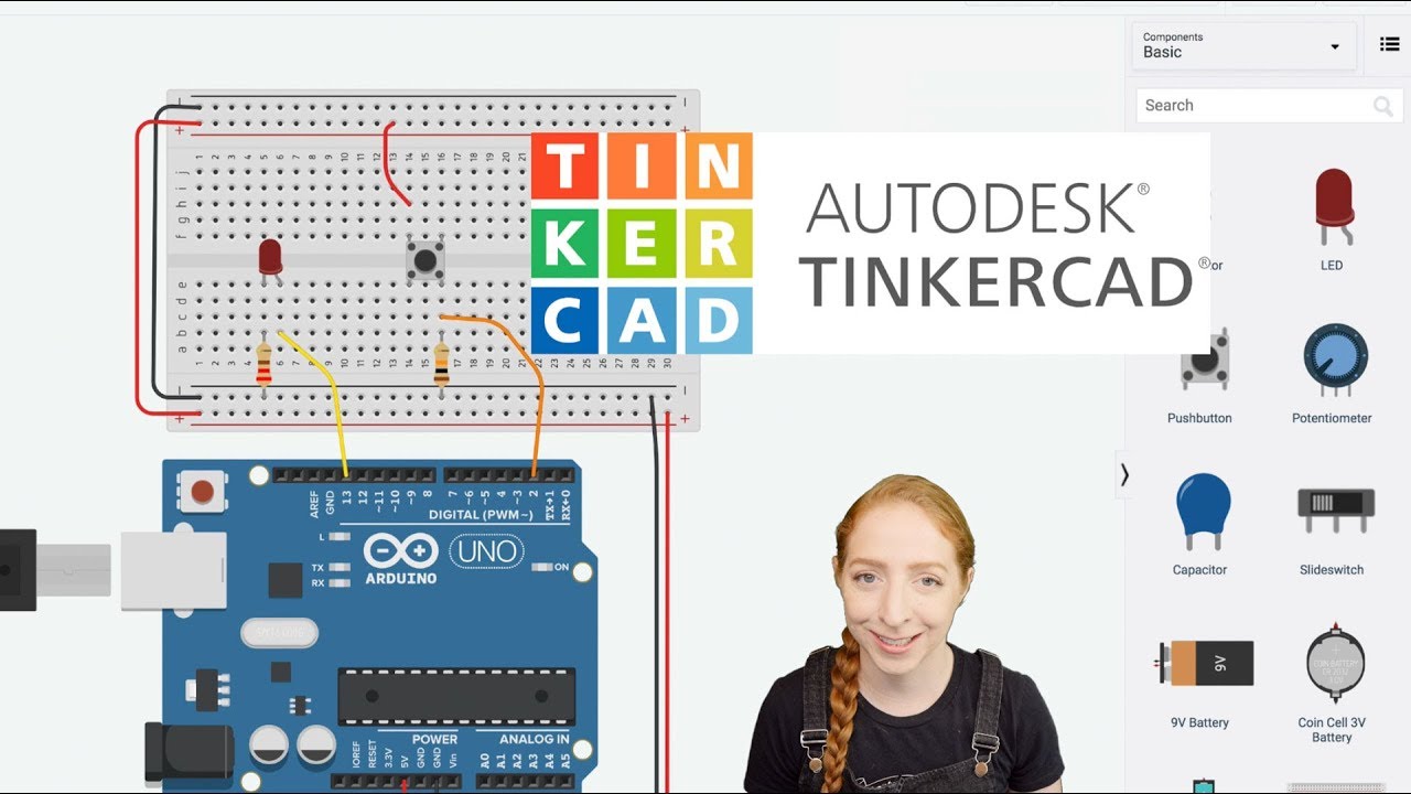
Pushbutton Digital Input With Arduino in Tinkercad
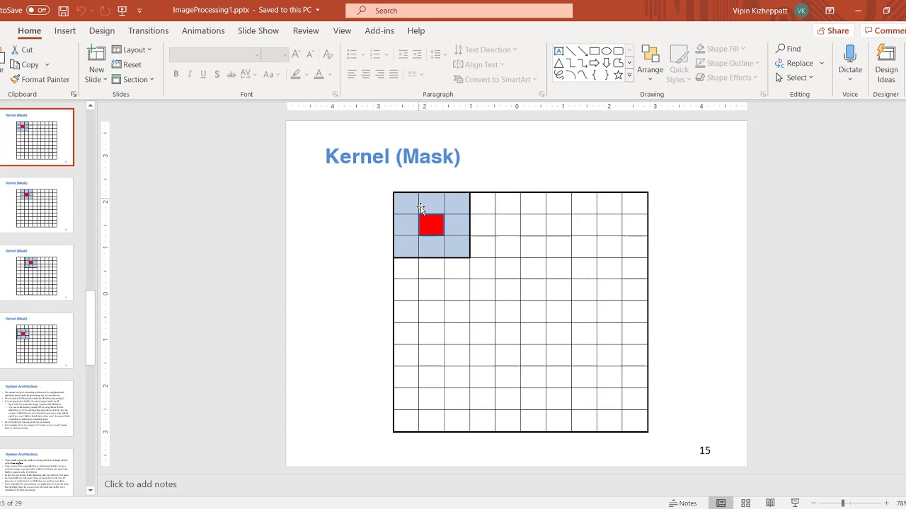
Image Processing on Zynq (FPGAs) : Part 2 Design of Line buffer
Arduino Analog Inputs
Arduino Programming Series - Tutorial 09 | Analog Input/Output Functions [in Hindi]

Part 4: Belajar Menggunakan ADC Arduino untuk Membaca Data Sensor dengan Mudah

Belajar Arduino #1 - Apa Itu Arduino?
5.0 / 5 (0 votes)
