Pump and Cargo Handling System

Marine Online
8 Oct 201714:41

Summary

TLDRThis script offers an in-depth look at the design and function of the aphromoo deep-well pump, highlighting its role in efficient cargo handling systems. It details the hydraulic systems by Frank Moon AAS, explaining the one pump per tank submerged cargo pumping system, which ensures safe and profitable operations with capacities ranging from 50 to 2000 cubic meters per hour. The script also covers the hydraulic system's open and closed-loop configurations, emphasizing the importance of clean hydraulic fluid for system efficiency and maintenance.

Takeaways

  • 🚀 The script discusses the design and function of aphromoo deep-well pumps, focusing on the hydraulic systems developed by Frank Moon AAS for liquid cargo handling.
  • 🛠 The one pump per tank submerged cargo pumping system was developed in cooperation with major chemical tanker operators, ensuring safe and profitable cargo handling with efficient stripping and cleaning.
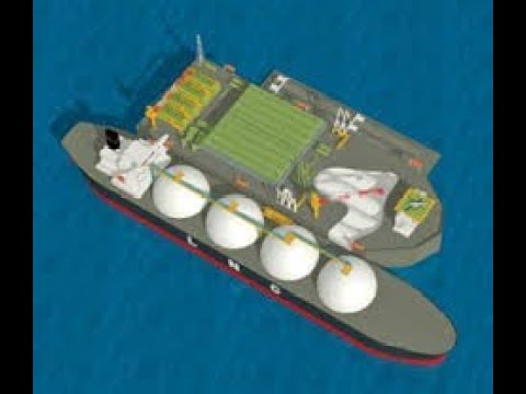
  • 🔱 Pump capacities vary from 50 to 2000 cubic meters per hour, with total discharge rates up to 15,000 cubic meters per hour, installed on various types of carriers including FPSOs and OBOS.
  • 🔄 The working principle of a centrifugal pump is explained, where the rotation of the impeller causes liquid to flow towards the periphery due to centrifugal force.
  • đŸ›Ąïž The cargo pump is supported by a deck trunk and includes a capacity control valve for remote and local operation, which regulates hydraulic pressure and oil flow to the motor.
  • 📈 The hydraulic system can be built as a central hydraulic main ring line system, either in a closed or open loop, with considerations for oil flow and pressure control.
  • đŸŒĄïž The importance of maintaining the hydraulic oil within a recommended temperature range (30-55 degrees Celsius) and water content (up to 0.03 percent) is highlighted for optimal performance.
  • 💧 The script emphasizes the need for clean hydraulic fluid to prevent reduced efficiency, excessive downtime, and increased maintenance costs.
  • 🛑 Emergency stop procedures are outlined for critical situations such as damage to hydraulic pressure pipes or hoses, uncontrolled spillage, or leakage during discharging.
  • 🔄 Post-operation procedures include reducing hydraulic system pressure, stopping main Power Packs, and ensuring one feed or jockey pump remains running to maintain overpressure in the system.
  • ⚙ The script provides detailed instructions for starting and stopping the hydraulic system, including checks on oil levels, cooling systems, and pressure settings.

Q & A

  • What is the purpose of the aphromoo deep-well pump?

    -The aphromoo deep-well pump is designed for the handling of liquid cargoes, ensuring safe and profitable cargo handling, efficient stripping, and tank cleaning.

  • Who developed the one pump per tank submerged cargo pumping system?

    -The one pump per tank submerged cargo pumping system was developed by Frank Moon AAS in cooperation with major chemical tanker operators.

  • What is the range of individual pump capacity in the Fram-o system?

    -Individual pump capacity in the Fram-o system varies between 50 and 2000 cubic meters per hour.

  • What types of vessels are the pumps installed on?

    -Pumps are installed on chemical carriers, product tankers, crude oil carriers, FPSOs, and OBO carriers.

  • How does the working principle of a centrifugal pump work?

    -The working principle of a centrifugal pump involves the rotation of the impeller, which causes the liquid to flow towards the periphery due to the centrifugal force, evacuating the center and allowing liquid from the suction line to fill the void.

  • What is the function of the deck trunk in the pump system?

    -The deck trunk supports the cargo pump and is welded to the deck, with all connections on the top cover plate for easy access and operation.

  • What is the role of the capacity control valve in the hydraulic system?

    -The capacity control valve regulates hydraulic pressure and oil flow to the motor according to the given discharge situation, allowing for remote and local operation of the cargo pump.

  • What is the purpose of the cofferdam in the hydraulic section?

    -The cofferdam completely segregates the hydraulic oil from the cargo, preventing any contamination and ensuring safe operation.

  • What are the two types of hydraulic systems mentioned in the script?

    -The two types of hydraulic systems mentioned are the open-loop system and the closed-loop system.

  • What is the recommended maximum water content in hydraulic oil?

    -The maximum recommended water content in hydraulic oil is 500 parts per million or 0.05 percent.

  • What should be checked before starting the main power packs in the hydraulic system?

    -Before starting the main power packs, one should check the hydraulic system tank oil level, ensure the cooling pump for hydraulic oil is running, verify the cooling fan for Power Packs is operating, confirm the necessary number of generators are running, adjust the potentiometer for system pressure to minimum, set the speed control valves for all consumers to minimum, and ensure the cargo pump cofferdams are purged.

Outlines

00:00

🛠 Deep-Well Pump Design and Hydraulic Systems

This paragraph introduces the design and function of the aphromoo deep-well pump, focusing on the hydraulic systems developed by Frank moon AAS for liquid cargo handling. It explains the one pump per tank submerged cargo pumping system, which is used on various types of vessels and has a wide range of individual pump capacities. The paragraph details the working principle of a centrifugal pump and the support structure of the cargo pump, including the deck trunk and the top cover plate with a capacity control valve. It also discusses the hydraulic system's components such as the supply line, return line, and the process of purging and stripping. The importance of maintaining proper seal conditions and monitoring systems is highlighted, along with the significance of the hydraulic section and the cofferdam that segregates hydraulic oil from the cargo.

05:03

🔄 Open and Closed Loop Hydraulic Systems

The second paragraph delves into the operation of open and closed-loop hydraulic systems used in cargo pumps. It explains how oil is delivered and returned in both systems, the role of the hydraulic oil tank, and the importance of an oil cooler and jockey pump. The paragraph outlines the advantages and disadvantages of each system, including simplicity and cost-effectiveness for open-loop systems and the smaller hydraulic tank requirement for closed-loop systems. It also emphasizes the importance of maintaining clean hydraulic fluid to avoid reduced efficiency and increased maintenance costs, providing specific recommendations for water content and cleanliness levels, as well as the ideal operating temperature for hydraulic oil.

10:07

🚀 Power Packs and System Operation Guidelines

This paragraph provides a detailed guide on the operation of power packs and hydraulic systems in cargo pumps. It discusses the importance of matching the number of power packs to the number of hydraulic motors in use, and provides a method to calculate the required oil flow for different pumps. The paragraph outlines pre-startup checks, including hydraulic system tank oil levels and the operation of cooling systems. It also describes the process of starting and stopping power packs, the importance of maintaining hydraulic pressure above cargo static pressure, and emergency stop procedures. The guidelines stress the need for system checks after shutdown and before restart, ensuring the system is properly refilled and vented before reoperation.

Mindmap

Keywords

💡Aphromoo deep-well pump

The 'Aphromoo deep-well pump' is a specific design of pump mentioned in the script, presumably for deep liquid extraction. This term is central to the video's theme as it sets the context for the type of pump technology being discussed. The script explains the design and function of this pump, which is integral to understanding the hydraulic systems developed for liquid cargo handling.

💡Principal components

The 'principal components' refer to the main parts of the hydraulic systems being described in the video. These are essential to understanding how the system operates as a whole. The script mentions that students should have a basic understanding of these components, which likely include the pump, impeller, and control valve, among others.

💡Tank operations

'Tank operations' encompass the processes involved in managing the storage and transportation of liquid cargo within tanks. The script illustrates how the hydraulic systems are designed to facilitate these operations, including safe and profitable cargo handling, efficient stripping, and tank cleaning.

💡Centrifugal pump

A 'centrifugal pump' is a type of pump that uses the centrifugal force generated by the rotation of an impeller to move liquids. The script describes the working principle of this pump, which is central to the hydraulic systems used for cargo pumping in various vessels.

💡Hydraulic system

The 'hydraulic system' is a key concept in the script, referring to the complete setup that uses pressurized fluids to power the cargo pumps. The script explains that the system can be built in either a closed or open loop, which is crucial for understanding the different configurations and their advantages and disadvantages.

💡Capacity control valve

The 'capacity control valve' is a component mentioned in the script that regulates hydraulic pressure and oil flow to the motor. This valve is essential for controlling the operation of the cargo pump, allowing for adjustments based on the discharge situation.

💡Cofferdam

A 'cofferdam' in the context of the script refers to a compartment or barrier that segregates the hydraulic oil from the cargo in the pump unit. This is important for preventing contamination and ensuring the integrity of the hydraulic system.

💡Stripping

'Stripping' is a term used in the script to describe the process of removing the last traces of cargo from a tank after the main discharge is complete. This is an important part of tank operations to ensure maximum efficiency and cleanliness.

💡Open-loop system

An 'open-loop system' is one of the hydraulic system configurations discussed in the script. It involves oil being circulated from a hydraulic oil tank, through the power packs, and back to the tank after use. This system is preferred for small systems due to its simplicity.

💡Closed-loop system

A 'closed-loop system' is the alternative configuration to the open-loop system. In this setup, only a small percentage of the used oil returns to the hydraulic tank, while the rest is reused directly. This system is preferred for large systems due to the smaller hydraulic tank size required.

💡Pilot line

The 'pilot line' is a small-diameter pipe installed to each capacity control valve, allowing for remote operation of the cargo pump from the cargo control room. This feature is crucial for efficient control and operation of the hydraulic system.

💡Emergency stop

The 'emergency stop' refers to a safety feature in the hydraulic system that can be activated in critical circumstances to immediately halt operations. The script advises that this should only be used in emergencies to avoid unnecessary stress on the system.

Highlights

Aphromoo deep-well pump design and principal components function explained.

Basic understanding of tank operations and hydraulic systems developed by Frank Moon AAS.

One pump per tank submerged cargo pumping system developed in cooperation with major chemical tanker operators.

The Fram-o system meets requirements for safe, profitable cargo handling, efficient stripping, and tank cleaning.

Individual pump capacity ranges from 50 to 2000 cubic meters per hour.

Total discharge rates can reach up to 15,000 cubic meters per hour.

Pumps are installed on various types of carriers including FPSOs and OBOS.

By January 2007, 48,000 cargo pumps had been delivered to 3030 vessels.

Working principle of a centrifugal pump demonstrated through impeller rotation and liquid flow.

Cargo pump supported by a deck trunk with connections on the top cover plate.

Specially developed control valve for remote and local operation of the cargo pump.

Pressure gauge indicates oil pressure to the motor, crucial for system monitoring.

Pipes and their functions in the hydraulic system explained for cargo pump operation.

Hydraulic system built as a central hydraulic main ring line system in closed or open loop.

Advantages and disadvantages of open-loop and closed-loop systems detailed.

Importance of maintaining hydraulic fluid cleanliness and recommended levels.

Recommended operating temperature for hydraulic oil and procedures for heating.

Procedures for starting and stopping the hydraulic system to ensure efficient operation.

Emergency stop and automatic shutdown conditions for system safety.

Pre-startup checks and post-operation procedures for hydraulic system maintenance.

Transcripts

play00:00

After successfully completing this lesson you should be able to describe

play00:04

how aphromoo deep-well pump is designed and explained the function of the

play00:08

principal components the student should have a basic understanding of tank

play00:13

operations this chapter illustrates the hydraulic systems developed by Frank

play00:18

moon AAS for the handling of liquid cargoes and briefly describes their

play00:23

basic operating principles

play00:45

the one pump per tank submerged cargo pumping system was developed by Frank

play00:50

Mon AS in close cooperation with the major chemical tanker operators the

play00:56

fram-o system satisfies requirements for safe and profitable cargo handling

play01:00

efficient stripping and tank cleaning individual pump capacity is vary between

play01:05

50 and 2000 cubic meters per hour and total discharge rates up to 15,000 cubic

play01:11

metres per hour pumps are installed on chemical carriers

play01:15

product tankers crude oil carriers floating production storage and

play01:20

offloading and floating storage and offloading units FPSOs and F SOS and oil

play01:27

/ bulk / or oboe carriers by January 2007 48,000 655 cargo pumps had been

play01:36

delivered to or ordered for a total of 3030 three vessels the working principle

play01:43

of a centrifugal pump can be seen here rotation of the impeller causes any

play01:48

liquid contained in it to flow towards the periphery because of the centrifugal

play01:52

force generated the center or eye of the impeller is thus evacuated and liquid

play01:58

from the suction line then flows in to fill the void

play02:03

the cargo pump is supported by a deck trunk welded to the deck all the

play02:07

connections are on the top cover plate to which a capacity control valve is

play02:11

also mounted for remote and local operation of the cargo pump this

play02:16

specially developed control valve regulates hydraulic pressure and oil

play02:19

flow to the motor according to the given discharge situation the pressure gauge

play02:24

indicates the oil pressure to the motor the pipes that connects the pump unit to

play02:30

the top cover plate

play02:34

click on the components below to learn more about the pipes deck the return

play02:39

from the cofferdam pipe if any leakages this will be discovered in the exhaust

play02:44

trap on the top cover plate during purging

play02:48

this is the supply line for the cargo pump it carries the oil from the Power

play02:52

Packs to drive the hydraulic motor this is the return line for the cargo

play02:58

pump it carries the oil back after it has been used to run the motor nitrogen

play03:04

or air is introduced during purging in order to ensure that the cofferdam is

play03:08

open and does not contain any cargo or oil

play03:12

cargo is forced through this line when the motor and impeller are running when

play03:18

emptying a tank nitrogen or air is introduced through the cargo discharge

play03:23

pipe and any final remaining product is forced up this line and on through the

play03:27

cargo manifold this is done to ensure that the tank and pump are cleared to

play03:32

the maximum possible extent on completion of the discharge the cargo

play03:36

pump is running during stripping the pump unit is mounted to the pipe

play03:42

stack / casing with a compact hydraulic motor located inside the casing the

play03:47

motor is surrounded by low pressure hydraulic oil a short independent shaft

play03:52

supported by bearings lubricated by hydraulic oil is connected to a single

play03:56

stage end suction centrifugal pump the hydraulic section is surrounded by a

play04:01

cofferdam that completely segregates the hydraulic oil from the cargo with a

play04:05

manual seal condition monitoring system this seal arrangement consists of a

play04:09

mechanical oil seal single cofferdam lip seal and a double cargo lip seal the

play04:15

cargo seal is exposed only to static head from the cargo any leakages in the

play04:19

cofferdam chamber will by purging with compressed air or nitrogen be blown

play04:24

through the cofferdam check pipe and collected in the exhaust trap a backstop

play04:28

unit is fitted to the shaft enabling cargo to be loaded through the pump

play04:32

Waring's are fitted between the impeller and the volute casing click on the

play04:37

buttons to learn more about the pump unit

play04:41

the hydraulic system is built as a central hydraulic main ring line system

play04:45

in either a closed or open loop hydraulic pumps deliver oil to the main

play04:50

pressure line from this named pressure line a number of hydraulic motors can be

play04:54

run provided that a sufficient number of Power Packs have been started in order

play04:59

not to over speed the hydraulic motors a speed control valve is installed

play05:03

upstream of each motor it is important to understand that the Power Packs

play05:07

deliver the oil and the cargo pumps our consumers

play05:12

in an open-loop system the hydronic oil is gravitated from a hydraulic oil tank

play05:17

to the Power Packs and further on via high-pressure lines to the cargo pumps

play05:22

and other consumers in the system after use the oil is transported via the

play05:26

return lines back into the hydraulic tank a pilot line is installed to each

play05:31

capacity control valve in order to remotely operate the cargo pump from the

play05:36

cargo control room an oil cooler is installed in the system in order to keep

play05:40

the oil temperature within desired limits a jockey pump is installed inside

play05:45

the hydraulic oil tank in order to maintain positive pressure in the

play05:49

hydraulic system and to avoid contamination of the oil with cargo if a

play05:53

leakage should occur in the cargo pump the jockey pump also serves as a cooling

play05:57

/ lubrication pump for the main hydraulic pumps this system requires a

play06:02

rather large hydraulic oil tank since all oil used is returned to this tank

play06:07

before pumped back again to the consumers due to this the open-loop

play06:11

arrangement is commonly used in small systems while the closed-loop

play06:15

arrangement is preferred for large systems

play06:19

advantages include simple air release procedure less piping leading to cost

play06:24

reduction and lower risk of leakage and a reduced number of components

play06:30

the disadvantage of this system is the size of the hydraulic tank in a

play06:35

closed-loop system the hydraulic oil is fed by a feed pump to the Power Packs

play06:40

and further on via high-pressure lines to the cargo pumps and other consumers

play06:44

in the system after use the oil is transported by the return line in a

play06:49

closed system only 10% of the oil goes back to the hydraulic tank while the

play06:54

rest is used directly on the Power Packs and back to the consumers a pilot line

play06:58

is installed to each capacity control valve in order to remotely operate the

play07:02

cargo pump from the cargo control room an oil cooler is installed in the system

play07:07

in order to keep the oil temperature within desired limits three feed pumps

play07:12

are installed on the hydraulic tank one running constantly one in standby mode

play07:16

and one in reserve when the cargo system is not in use the selected feed pump is

play07:21

delivering low pressure sufficient to maintain positive pressure in the

play07:25

hydraulic system and to avoid contamination of the oil with cargo if a

play07:29

leakage should occur in the cargo pump when the system is in use the second

play07:33

feed pump starts automatically increasing the pressure such that in

play07:37

addition to leak prevention 10% of the total oil capacity is returned to the

play07:42

hydraulic tank the third pump is brought online in the event of a problem with

play07:46

one of the regular pumps since only 10% of the oil used is returned to the

play07:50

hydraulic tank this system requires a much smaller hydraulic oil tank than the

play07:55

open system the closed loop system is commonly used in big systems

play08:02

the advantage of this system is the size of the hydraulic tank

play08:07

disadvantages include a more complex air release procedure more piping and more

play08:13

components note in the older systems to feed pumps were installed one was

play08:18

running in standby and two during normal operation hydraulic pumps motors and

play08:25

controls are devices requiring close tolerances controlled wear surfaces

play08:29

accurate finish and an adequate supply of clean hydraulic fluid contaminated

play08:34

oil will not provide proper lubrication and is a leading contributor to reduced

play08:39

efficiency excessive downtime and increased maintenance cost the maximum

play08:43

recommended water content is 300 parts per million or 0.03 percent and must

play08:50

under no circumstances be above 500 parts per million or 0.05 percent

play08:56

if in doubt please contact fram-o recommended cleanliness level is code 16

play09:02

over 12 according to iso for 406 or c top PR 2016 over 12 means that the

play09:11

number of particles above 5 micron in one milliliter is between 320 and 640

play09:17

and the number of particles above 15 micron in one milliliter is between 20

play09:22

and 40 the recommended operating temperature of

play09:27

the hydraulic oil is between 30 and 55 degrees Celsius if the oil temperature

play09:33

is below 20 degrees Celsius circulate the oil through the heating and venting

play09:38

valve installed in the system for heating with only one power pack running

play09:42

until the desired oil temperature is reached note do not exceed 100 bar

play09:47

circulating pressure during heating even though most operations which happen

play09:53

when you push the start button on a power pack are automatic it is important

play09:58

to know what actually happens and which items need to be checked prior to

play10:02

startup in order to perform an economical discharge and minimize wear

play10:06

and tear on the equipment it is very important that the number of power packs

play10:10

used corresponds to the number of hydraulic motors used as previously

play10:15

mentioned it is important to understand that the various pumps used in the

play10:18

system are consumers while the Power Packs are in the delivery business this

play10:23

means that one pump requires an amount of oil in order to operate and the power

play10:27

pack has to supply the amount needed in your manual onboard you will find a

play10:32

table where you can find out how much oil flow each hydraulic motor needs and

play10:36

how much oil flow each power pack delivers see under technical data in

play10:41

your manual when planning a discharge just add the oil consumption of the

play10:46

number of pumps to be used at the same time and choose number of Power Packs

play10:50

so the flow delivered is a little above the flow required

play10:55

for example during discharging you will use two SD 300 pumps and one ballast

play11:01

pump how many power packs need to be run the

play11:04

consumption of an SD 300 pump is 938 liters per minute two pumps will

play11:11

therefore together require 1876 liters per minute the ballast pump consumes 246

play11:18

liters per minute this gives a total oil consumption of two thousand one hundred

play11:23

and twenty two liters per minute a small power pack delivers 697 liters per

play11:28

minute to small packs will therefore together deliver 1394 liters per minute

play11:34

one big power pack will deliver 831 litres per minute these units will

play11:40

deliver a total of two thousand two hundred and twenty five litres per

play11:44

minute we therefore need to run two small and one big power pack to meet the

play11:49

demand before starting the main power packs

play11:52

check the following hydraulic system tank oil level that the cooling pump for

play11:57

hydraulic oil cooler is running that the cooling fan for Power Packs is running

play12:01

that the necessary number of generators is running that the potentiometer for

play12:05

system pressure is in minimum position that the speed control valves for all

play12:09

consumers are in minimum position that the cargo pump cofferdams are purged

play12:13

start the main Power Packs after an operation is completed all

play12:19

consumers have been stopped in the main power packs are no longer required the

play12:23

system should be stopped as follows reduce the hydraulic system pressure to

play12:27

minimum stop the main Power Packs stop the cooling water pump and fan stopped

play12:32

the excess generator sets stop the feed pump and restart in low speed this

play12:38

happens automatically after approximately 10 minutes always leave

play12:42

one of the feed or jockey pumps running in low speed to maintain over pressure

play12:46

in the hydraulic system if by accident cargo should leak into the hydraulic oil

play12:51

system when the Power Packs are stopped the mixture of oil and cargo would ruin

play12:55

the plant to prevent this the hydraulic oil pressure must always be higher than

play13:00

the cargo static pressure when the hydraulic system is not in operation one

play13:04

of the feed pumps will keep a hydraulic pressure of approximately 4 bar 1 of the

play13:09

feed or jockey pumps must always be running in low speed and all valves in

play13:13

the main return line and in front of all cargo pumps and other consumers must be

play13:17

open it is important that emergency stop

play13:21

buttons are used in emergency situations only and not for routine operational

play13:26

stopping of the system an emergency stop stresses the system and should be

play13:31

avoided except in critical circumstances

play13:36

emergency stop button should be activated when the following conditions

play13:39

occur damage to the hydraulic pressure pipes or hoses that leads to leakage

play13:44

critical pressure pulsation in the system known as hunting critical

play13:49

vibration on the Power Packs damage to the cargo lines uncontrolled spill or

play13:54

leakage during discharging the following conditions should lead to

play13:59

automatic shutdown of the system low low oil level in tank closed valve in return

play14:05

line in closed system low feed pressure in closed systems feed pump failure when

play14:11

running at high speed after a shutdown the error must be located and repaired

play14:16

before restart before restart reset system refill oil

play14:23

if necessary in accordance with normal procedures event the system thoroughly

play14:28

and startup in accordance with normal procedures

Rate This
★
★
★
★
★

5.0 / 5 (0 votes)

Étiquettes Connexes
Deep-Well PumpsCargo HandlingHydraulic SystemsTank OperationsFram-o TechnologySafety ComplianceEfficient StrippingTank CleaningPump CapacityHydraulic MotorMaintenance Tips
Besoin d'un résumé en anglais ?