UML Diagram For Software Engineering | Unified Modelling Language Diagram | Simplilearn
Summary
TLDRThis video script delves into the crucial role of UML diagrams in software engineering, highlighting their use in approximately 70% of major software projects. UML diagrams, likened to a map for building software, enhance design documentation, improve efficiency, and reduce errors by 35%. The script explores different types of UML diagrams, including structural and behavioral, and demonstrates creating a UML diagram with a library management system example. It emphasizes the importance of understanding associations in UML for accurately modeling system interactions and architecture.
Takeaways
- 📚 UML diagrams are essential in software engineering, underpinning about 70% of major software projects by providing a visual blueprint for system design and communication.
- 🛠️ UML stands for Unified Modeling Language, a set of graphical notation techniques developed in the 1990s, which has become a standard for visualizing and documenting software systems.
- 🔍 UML diagrams can significantly reduce errors in software plans by up to 35%, leading to the creation of better software with fewer issues.
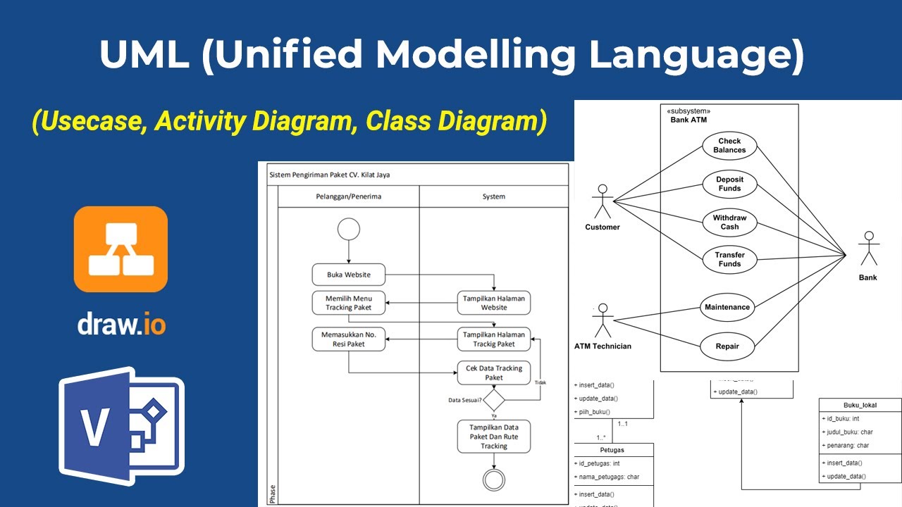
- 🔄 UML diagrams come in different types, including structural and behavioral diagrams, each serving a specific purpose in illustrating how a system is built and operates.
- 🔑 Structural diagrams include class, component, object, and package diagrams, which show how the parts of a system are organized and related.
- 🔄 Behavioral diagrams, such as use case, sequence, activity, and state machine diagrams, represent the dynamic aspects of a system, including the flow of control and states.
- 👥 UML facilitates collaboration and understanding among diverse team members and stakeholders by providing a common visual language to discuss system design.
- 🛑 UML diagrams help in identifying potential issues early in the development process, contributing to a more efficient workflow and reduced error rates.
- 🔑 Creating a UML diagram involves identifying main classes, defining their attributes and operations, and illustrating the relationships between them, such as inheritance, association, and dependency.
- 🔗 Associations in UML diagrams represent relationships between classes and can be simple, bidirectional, unidirectional, or more complex forms like aggregation and composition.
- 🏆 Understanding UML associations is crucial for accurately modeling the relationships between classes, which is essential for designing system architecture and comprehending object interactions within the system.
Q & A
What is the significance of UML diagrams in software engineering?
-UML diagrams are crucial in software engineering as they help in visualizing and documenting software systems, facilitating better understanding within teams, effective communication with stakeholders, and reducing errors by 35% in plans.
How do UML diagrams help in the planning and execution of software projects?
-UML diagrams assist in the planning stages by providing a clear and concise way to communicate complex software designs and in the execution by identifying potential issues early in the development process, leading to a more efficient workflow.
What are the two main types of UML diagrams?
-The two main types of UML diagrams are structural diagrams, which include class diagrams, component diagrams, object diagrams, and package diagrams, and behavioral diagrams, which include use case diagrams, sequence diagrams, activity diagrams, state machine diagrams, and interaction diagrams.
What is the role of UML in enhancing collaboration and understanding among team members?
-UML diagrams help in enhancing collaboration by visualizing complex systems, enabling easier teamwork and ensuring that all stakeholders have a common understanding of the system.
How can UML diagrams be used to improve the efficiency and reduce errors in software development?
-UML diagrams help in identifying potential issues early in the development process, which contributes to a more efficient workflow and reduced error rates by providing a standardized approach to visualize system architecture and processes.
What is the purpose of class diagrams in UML?
-Class diagrams in UML represent the structure of a system by showing classes, their attributes, operations, and the relationships between them, such as inheritance, association, and dependency.
Can you explain the concept of associations in UML diagrams?
-Associations in UML diagrams represent the relationships between classes, showing how objects of one class interact with objects of another class. They can be simple, bidirectional, unidirectional, or more complex forms like aggregation and composition.
What is the difference between aggregation and composition in UML diagrams?
-Aggregation represents a whole-part relationship where the parts can exist independently of the whole, indicated by a hollow diamond. Composition implies a strong ownership where if the whole is destroyed, the parts are destroyed too, indicated by a filled diamond.
How does the use of UML diagrams contribute to the creation of better software?
-UML diagrams contribute to the creation of better software by providing a visual model of the system, which helps in preventing mistakes, improving design and documentation, and facilitating effective communication among team members and stakeholders.
What is the process of creating a UML diagram?
-The process of creating a UML diagram involves identifying main classes, defining attributes and operations for these classes, illustrating relationships between classes, and using symbols or labels to show the nature of the relationships, such as multiplicity and navigation.
How can someone interested in software engineering enhance their skills and switch careers?
-Individuals interested in software engineering can enhance their skills and switch careers by enrolling in postgraduate programs in full-stack web development, like the one offered in collaboration with ctech ctma, which provides modern coding techniques and the necessary skills to become a full-stack technologist.
Outlines
📚 Introduction to UML Diagrams in Software Engineering
This paragraph introduces the Unified Modeling Language (UML) as a fundamental tool in software engineering, utilized in approximately 70% of major software projects. UML diagrams are likened to maps, translating complex ideas into actionable software plans and reducing errors by 35%. The paragraph emphasizes the importance of UML in various aspects of software development, including communication, design documentation, efficiency, and error reduction. It also briefly touches on the educational aspect, suggesting a postgraduate program for career switchers to software engineering, which is offered in collaboration with ctech ctma and includes intensive modern coding techniques.
🔍 Exploring UML Diagram Types and Their Creation Process
This paragraph delves into the different types of UML diagrams, categorizing them into structural and behavioral diagrams. Structural diagrams include class, component, object, and package diagrams, which represent system elements and their relationships. Behavioral diagrams, such as use case, sequence, activity, state machine, and interaction diagrams, illustrate the dynamic aspects of a system. The paragraph also outlines the step-by-step process of creating a UML diagram, starting with identifying main classes, defining attributes and operations, and illustrating relationships like inheritance, association, and dependency. An example of a library distribution system UML diagram is provided, demonstrating the application of these concepts.
🔄 Understanding UML Associations and Their Significance
The final paragraph focuses on the concept of associations in UML diagrams, which are critical for accurately modeling relationships between classes. It discusses various types of associations, including simple, unidirectional, bidirectional, aggregation, and composition. Each type of association is explained with its representation in a UML diagram, such as lines with or without arrows, and diamonds indicating aggregation or composition. The paragraph concludes by emphasizing the importance of understanding associations for designing system architecture and comprehending object interactions within the system.
Mindmap
Keywords
💡UML Diagram
💡Software Engineering
💡Structural Diagrams
💡Behavioral Diagrams
💡Class Diagram
💡Association
💡Multiplicity
💡Error Reduction
💡Collaboration
💡Full Stack Developer
💡Simply Learns
Highlights
UML diagrams underpin approximately 70% of major software projects, serving as a critical tool in software engineering.
UML diagrams help convert big ideas into plans for software development, potentially reducing errors in plans by 35%.
UML diagrams come in different types, each serving a distinct part of the software-making process.
UML diagrams are crucial for building strong, flexible, and effective software, used in over half of successful software projects globally.
UML, or Unified Modeling Language, is a set of graphical notation techniques for visual software system modeling.
UML was developed in the 1990s and has become a standard in software engineering for visualizing and documenting systems.
UML diagrams play a key role in software development, facilitating clear communication of complex designs.
UML enhances design and documentation, providing a standardized approach to system architecture visualization.
UML diagrams improve efficiency and reduce errors by identifying potential issues early in the development process.
UML aids in facilitating collaboration and understanding among diverse team members and stakeholders.
UML diagrams are instrumental in planning and designing system architecture and in effective communication.
There are two main types of UML diagrams: structural and behavioral, each with specific subtypes for different aspects of system representation.
Structural diagrams include class, component, object, and package diagrams, showing system structure and class instances.
Behavioral diagrams such as use case, sequence, activity, and state machine diagrams represent the dynamic aspects of a system.
Interaction diagrams and deployment diagrams focus on the interaction between objects and the physical deployment of software components.
Creating a UML diagram involves identifying main classes, defining attributes and operations, and illustrating relationships.
Associations in UML diagrams represent relationships between classes, with different types indicating navigation and ownership.
Understanding associations in UML is crucial for accurately modeling system interactions and object relationships.
The tutorial concludes with an overview of different types of associations in UML diagrams and their significance in system modeling.
Transcripts
venturing into the world of software
engineering we encounter a critical tool
that underpins approximately 70% of
major software projects the uml diagram
it's like a map for building software
and is used in about 70% of big software
projects these diagrams help turn Big
Ideas into plans that can actually be
made into software think of uml diagrams
like a guide book for software they help
prevent mistakes in fact a study shows
that using them can cut down errors in
plans by 35% that's a big deal because
it means making better software with
fewer problems uml diagrams comes in
different types each for a different
part of making software some show how
the parts of a system fit together while
others show how different parts talk to
each other they use a special kind of
picture language to show all this we're
going to see how these diagrams help
make ideas real which is why they are
used in more than half of the successful
software projects around the world
they're super important for building
strong flexible and and effective
software so let's dive in and learn how
they work and why they are so important
in making cool softwares and just a
quick info for you uml diagrams are like
a guide book for software so
professional who wants to switch careers
with software engineering by learning
from the experts can try giving a sh to
Simply learns postgraduate program and
fullstack web development he can
accelerate his career as a software
developer through this postgraduate
program in full St web development
course in collaboration with ctech ctma
in just a few months month you will
learn modern coding techniques with boot
camp level intensity and gain all you
need to be a full stack technologist the
course link is mentioned in the
description box that will navigate you
to the homepage where you can find a
complete overview of the program being
offered take action up skill and get
ahead so without any further Ado let's
get started so the first thing we will
learn today is uml uml or unified
modeling language it is a set of
graphical notation techniques to create
visual models of Software System systems
it helps in depicting the structure and
behavior of systems in systematic manner
it is developed in the 1990s and uml has
become a standard in software
engineering for visualizing and
documenting software systems so this was
about uml now moving to the importance
of uml in software engineering so the
first importance is that it plays key
role in software development uml
diagrams provide a clear and concise way
to communicate complex software designs
they facilitate better understanding
within teams and effective communication
with external stakeholders now the next
point is it enhances design and
documentation so uml AIDS in both the
design and documentation phase of
software engineering it provides a
standardized approach to visualize
system architecture and processes and
the next key role is improvising
efficiency and reducing errors so uml
diagrams help in identifying potential
issues early in the development process
and they contribute to a more efficient
workflow and reduced error rates now
moving to the next key role that is
facilitating collaboration and
understanding so by visualizing complex
systems uml diagrams enable easier
collaboration among diverse team members
they help in ensuring all stakeholders
have a common understanding of the
system and uml in action there's a key
role such as planning that explains how
uml was used in the initial planning
stages and the design that shows how uml
diagrams assisted in designing the
system architecture and the
communication uml facilit effective
communication among team members and
stakeholders so this was the importance
of uml diagrams across all the software
teams now we'll move to the types of uml
diagrams that are available in the
market so mainly uml has two types of
diagrams one is structural and other is
the behavioral diagrams so structural
diagrams contains class diagrams
component diagrams object object
diagrams and they represent instances of
classes at a specific Moment In Time an
object diagram showing various
instantane objects and their
relationships and there are package
diagrams also that illustrate how
different packages and their elements
are organized in a system and then comes
a package diagram so a package diagram
displaying the systems packages and
dependencies and then we have behavioral
diagrams that contains use case diagrams
sequence diagrams and activity diagrams
that show the dynamic flow of control
from activity to activity within the
system and an activity diagram depicting
the flow of activities in a process or
workflow is defined as behavioral
diagram and there are State machine
diagrams that represent the states and
transs of a system or its component so a
state diagram illustrating the various
States an object goes through and the
transition based on events and then
there are interaction diagrams as you
can see in the flow of the diagram that
is uml diagram type there are
interaction diagrams and below that only
there are communication diagrams that
focus on the interaction between objects
but highlight their organization and
relationships and a communication
diagram that shows objects their links
and the message is exchanged and then we
have timing diagrams so timing diagram
represent the behavior of objects
throughout a given period and the
interactions in terms of timing
constraints and a timing diagram showing
the state changes and interactions of
objects over time and then we have
deployment diagram that shows the
physical deployment of artifacts or
nodes a deployment diagram displaying
the configuration of runtime processing
elements and the software components
processes and objects that live on them
so this was all about the uml diagram
type so the main types are structural
and behavioral diagrams and below that
we have other class diagram profile
diagram package diagram object diagram
component diagram and under behavioral
we have sequence diagram timing diagram
State machine diagram and interaction
diagram so these are the main types now
we'll move to create a uml diagram so
this is a stepbystep process to create a
uml diagram so the first step is
identify main classes so we'll start
with the first step that is identify
main classes we'll start with
determining the primary classes in your
system then we'll Define attributes and
operations for these classes only
that is for each class we will Define
its attributes that is properties and
operations that are functions or methods
and then we will illustrate
relationships that is we will show the
relationship between classes such as
inheritance Association and dependency
and in uml that is Unified modeling
language associations represent the
relationships between classes they show
how objects of one class connect and
interact with objects of another class
so let's see the diagram so our first
diagram is book so book is the class
here and then we have attributes that is
title so what is the title of the book
and then we have press the colon and
then the data type of title that is
string and then we have author then
colon string and then the ISBN number of
the book and then we have the method
here that is check availability and here
in this method we will check whether the
book is available in the library or not
so here we will create the library
distribution system as a uml diagram so
we have created the class book and its
attributes and methods and now we will
create a class called member so the
member who is coming to the library to
borrow a book so now we will Define its
attributes and methods so the first
attribute we will Define is name and
it's of data type string and then we
have membership ID and then loan records
and we have defined a method here that
is borrow book and then we have another
class that is loan so we will Define its
attribute that is loan date due date
return date and the next is the column
for methods and here we will Define the
method that is renew loan and in this
you could see the plus signs and the
hashtag signs so here the plus sign
indicates that the attributes are public
to all the classes so they can be
inherited or associated with other
classes and the hash signs that is in
the member class so it is the protected
attribute that is loan records so
records can't be accessed by other items
or the other classes so now we will see
the association between these classes so
first we'll see the association between
member and book class so this
Association is represented by the borrow
book method so operation in the member
class it indicates that a member can
borrow a book and in the uml diagram
this would typically be shown as a line
connecting the member and book classes
and the nature of this Association can
be further detailed with multiplicity
which indicates how many instances of
one class can be associated with one
instance of the other class for example
a member can borrow multiple books and a
book can be Borrowed by multiple members
so for that we have Associated both the
book and the member class and then we'll
see the association between member and
Loan class so the loan records attribute
in the member class represents this
Association this shows that a member has
a relationship with loan that is a
member has zero or more loan records in
the uml diagram a line would connect
member and Loan often with multiplicity
indicating that one member can have
multiple loans and then we have
association between book and Loan so
this Association is implicit in the
context of a library system each loan
record would be associated with a
specific book indicating which book is
Unown in the uml diagram a line would
connect the book and Loan classes
typically with the multiplicity of one
that is each loan is for one book so the
associations are visualized as lines
connecting the classes and the ends of
the lines can have symbols or labels
showing the nature of the relationship
like arrows or multiplicity indicators
so the types of arrows you use to
represent an association depends on the
nature of the relationship between the
classes so Association without
navigation that is bidirectional or
unired when objects of both classes can
access each other and the direction of
the relationship isn't emphasized so a
plain line without arrows between member
and the book class in the case of boring
books you can see that this can be a
plain line as both the member and book
are aware of each other in the
transaction so this was the
unidirectional or bidirectional so both
can have a transaction between them and
then we have association with navigation
that is unidirectional so when objects
of one class can access objects of the
other class but not vice versa so for
this we will draw a line with a single
arroe head pointing towards the class
that is being accessed for example if we
see here if only members need to have
direct knowledge or access to their loan
records but not the other way around you
would use a line with a arrow pointing
from member to the loan class so this
was about this uml diagram that is
Library management system so now moving
to the next topic that is Association in
uml diagrams so here we will understand
association between the classes and how
we can access their methods and
attributes so certainly understanding
associations inl that is Unified
modeling language is crucial for
accurately modeling the relationships
between classes in a system now we'll
break down different types of
Association commonly used in uml
diagrams so the first is simple
Association so this represents a general
relationship where instances of one
class are connected to instance of
another class for this type of
Association we usually represent this
with a simple line without arrows
indicating a bidirectional or
non-directional relationship so customer
class associated with an order class so
customer can order one order or a order
is associated with a customer so this
was about the simple associ
now moving to the next that is
association with navigation that is
unidirectional so it indicates that one
class can navigate to or access another
class but not vice versa so to indicate
this type of navigation we use a line
with an arrow pointing towards the class
that is being accessed now moving to the
next that is bidirectional Association
so both classes are aware of each other
and can navigate to each other so to
represent this we'll use a line with
arrow heads on both ends or no
arrowheads at all so this was about the
bir directional Association now moving
to the next that is aggregation so a
special form of Association that
represents a whole part relationship but
without strong ownership the parts can
exist independently of the whole and for
this aggregation we will use a line with
a hollow Diamond at the whole class end
so this was about aggregation now moving
to the next that is composition so
stronger form of aggregation implying
strong ownership if the whole is
destroyed the parts are destroyed too so
to represent them will use a line with a
fill Diamond at the whole class end for
example a house class that is whole and
a room class that is a part if the house
is destroyed so the rooms cease to exist
so the rooms will also be destroyed so
this is about the composition
Association and there are also other
associations that is reflexive
multiplicity but these are not generally
used in drawing uml diagrams so in
conclusion when creating a uml diagram
understanding these associations helps
in accurately modeling how objects in
the system interact and depend on each
other they also assist in designing the
systems architecture and are critical
for developers to understand the
Dynamics of object interactions within
the system so each type of Association
in uml diagrams it's a unique way to
represent different kinds of
relationships that can exist between
classes contributing to a comprehensive
and clear model of the system structure
and behavior and with this we have come
to the end of this tutorial hope you
guys found it informative and helpful
then like share and subscribe till then
stay safe and keep
learning
Voir Plus de Vidéos Connexes
Project Based Internship Klinikgo Health System Analyst - Company Coaching Video 1
Introduction to UML
TOPCIT Software | 05. Software Requirements Analysis
Top 6 Tools to Turn Code into Beautiful Diagrams
Visualising software architecture with the C4 model - Simon Brown, Agile on the Beach 2019
What is Domain Model and Conceptual Classes?. Tutorial
5.0 / 5 (0 votes)