CONECTAR DOS REDES A UNA IMPRESORA EN PACKET TRACER 7
Summary
TLDRThis video tutorial demonstrates how to set up a simple network topology using a Layer 3 switch, enabling both Network 1 and Network 2 to share a printer. It uses a crossover cable for the physical connection and configures the logical part by assigning IP addresses and subnet masks to the devices, including a router, PCs, a laptop, and the printer. The video also guides through the process of setting up gateways and testing connectivity using ping commands, ensuring all devices can access the printer.
Takeaways
- 🔌 The video demonstrates setting up a simple network topology to share a printer between two networks.
- 💻 It uses a 'shooter' to interconnect the two networks, with one PC representing the first network.
- 🔄 A 24-port switch, a PC, a laptop, and the printer are used to represent the second network.
- 📡 The physical setup involves using a straight-through cable for the printer and switch, and a crossover cable for the switch and the router.
- 🔩 The router's Fast Ethernet 01 port is used for the network connection.
- 🛠️ The logical configuration starts with entering the router's command-line interface and entering privileged mode.
- 📍 IP addresses are assigned to the router's interfaces, including a Class C IP address for the first set and a gateway IP for the second set.
- 🔄 The interfaces are activated using the 'no shutdown' command.
- 🏢 For the PCs and laptop, IP addresses are assigned manually with automatic subnet mask generation and the gateway set to the router's interface IP.
- 🖨 The printer is configured similarly, but also includes setting a gateway to the Fast Ethernet 01 IP.
- 📝 The script includes troubleshooting steps, such as re-attempting connections when the first ping fails, indicating a delay in the router establishing the connection.
- 🔍 The video concludes with successful ping tests from different devices to the printer, confirming the network setup's functionality.
Q & A
What is the main purpose of the video?
-The main purpose of the video is to demonstrate how to set up a simple network topology that allows both Network 1 and Network 2 to use a shared printer.
What device is used to interconnect the two networks?
-A 'shooter' or a router is used to interconnect the two networks.
What type of cable is used to connect the printer to the switch?
-A straight-through cable is used to connect the printer to the switch.
What type of cable is used to connect the PC to the router?
-A crossover cable is used to connect the PC to the router.
Which port on the router is used for this network setup?
-Fast Ethernet 01 port is used for this network setup.
How is the IP address assigned to the interfaces on the router?
-The IP addresses are assigned through the configuration mode of the router, with one interface getting an IP of a Class C network and the other interface getting an IP that will be used as the gateway.
What command is used to activate an interface on the router?
-The 'no shutdown' command is used to activate an interface on the router.
How are the IP addresses assigned to the end devices like PCs and the printer?
-The IP addresses for the end devices are manually assigned, with the subnet mask being generated automatically, and the gateway being set to the IP address of the router interface.
What is the significance of assigning a gateway to the devices?
-Assigning a gateway allows the devices to communicate with networks outside their local network, enabling them to access the shared printer.
How is the printer configured to be accessible from both networks?
-The printer is configured with a gateway that points to the IP address of the Fast Ethernet 0/1 port, allowing it to be accessible from both networks.
What troubleshooting method is used to test the connectivity between devices?
-The 'ping' command is used to test the connectivity between devices, ensuring that they can communicate with the printer.
Outlines

Cette section est réservée aux utilisateurs payants. Améliorez votre compte pour accéder à cette section.
Améliorer maintenantMindmap

Cette section est réservée aux utilisateurs payants. Améliorez votre compte pour accéder à cette section.
Améliorer maintenantKeywords

Cette section est réservée aux utilisateurs payants. Améliorez votre compte pour accéder à cette section.
Améliorer maintenantHighlights

Cette section est réservée aux utilisateurs payants. Améliorez votre compte pour accéder à cette section.
Améliorer maintenantTranscripts

Cette section est réservée aux utilisateurs payants. Améliorez votre compte pour accéder à cette section.
Améliorer maintenantVoir Plus de Vidéos Connexes

How to Build a LAN (Local Area Network) | Windows and Mac

TUTORIAL - CARA MEMBUAT JARINGAN LAN DI RUMAH ATAU KANTOR
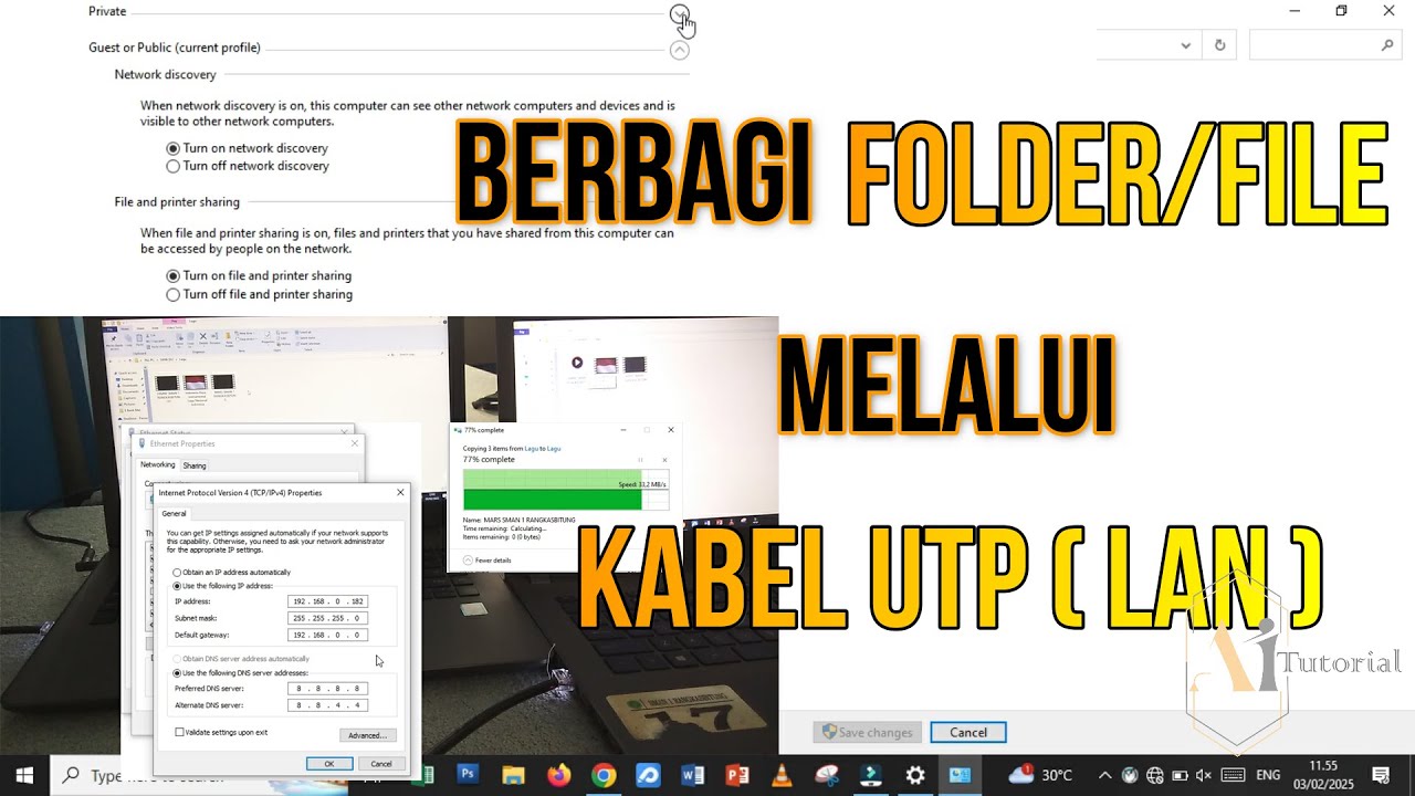
CARA TRANSFER FOLDER/FILE MENGGUNAKAN KABEL LAN
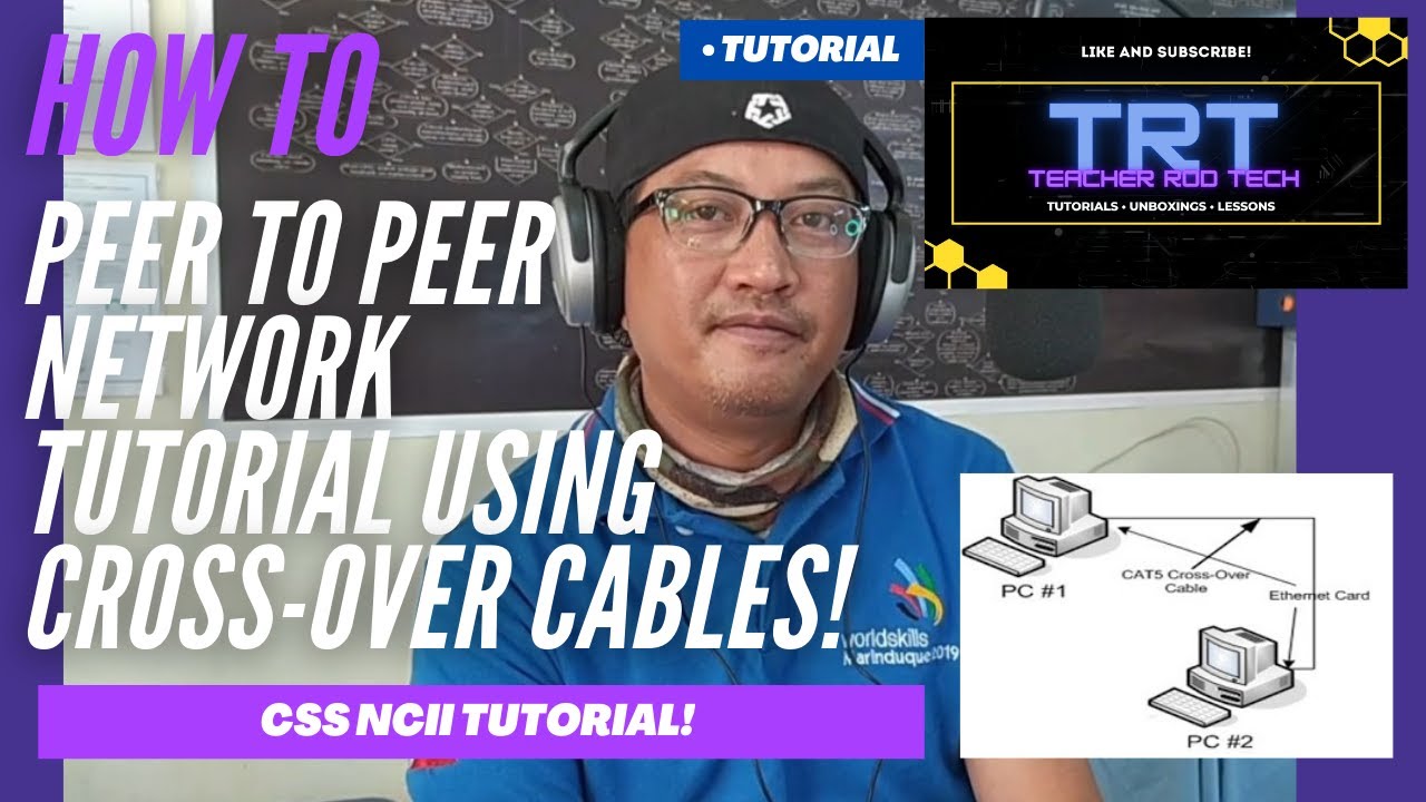
Peer To Peer Network Tutorial using Crossover Cables (Tagalog)
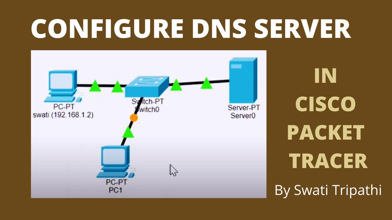
DNS Server Configuration in Cisco Packet Tracer
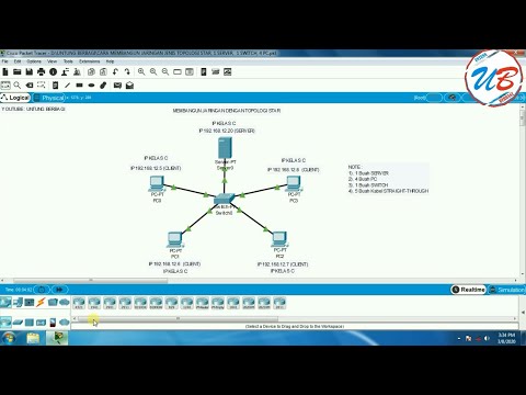
cara membangun jaringan jenis topologi star, 1 server, 1 switch, 4 pc pada cisco packet tracer
5.0 / 5 (0 votes)
