Simple Combination Circuit with 8 resistors
Summary
TLDRThis video provides a detailed walkthrough for solving an electrical circuit problem involving eight 1-ohm resistors and a 6-volt power supply. The instructor methodically demonstrates how to simplify the circuit using series and parallel combinations, calculate the total resistance and current, and determine individual voltages and currents for each resistor. Emphasis is placed on step-by-step calculations, including series sums, parallel formulas, and Ohm’s law, ensuring clarity for learners. The explanation is thorough yet accessible, offering a clear review for those revisiting the problem and helping viewers build confidence in analyzing complex resistor networks.
Takeaways
- 😀 The problem involves a circuit with 8 resistors, each having a value of 1 ohm, connected in a combination of series and parallel.
- 😀 The total voltage supplied to the circuit is 6 volts.
- 😀 The first step is to simplify the circuit by combining series resistors: R1 and R4, R3 and R5.
- 😀 Parallel resistors like R7 and R8 are combined using the formula R = (R1 * R2) / (R1 + R2).
- 😀 The next step involves combining the three groups (R_A, R2, R_B) in parallel to find R_D using the reciprocal formula for parallel resistances.
- 😀 Total resistance of the circuit after simplification is calculated to be 2 ohms.
- 😀 Total current in the circuit is found using Ohm's law: I_total = V_total / R_total = 3 A.
- 😀 Voltages across series resistors (R_D, R6, R_C) are calculated by multiplying the current by their resistance.
- 😀 Currents in parallel resistors are determined by dividing the voltage across them by their individual resistances.
- 😀 Individual resistor voltages and currents are then calculated for each resistor, with verification to ensure the total current and voltage match the given values.
- 😀 Series resistors share the same current, while parallel resistors share the same voltage.
- 😀 The video emphasizes a step-by-step approach to solving complex resistor networks and serves as a review for those familiar with the problem.
Q & A
What is the first step to solving the circuit problem in the video?
-The first step is to compress the diagram and solve for the total resistance by combining resistors in series and parallel as needed.
How are resistors R1 and R4 combined in the circuit?
-Resistors R1 and R4 are connected in series, so their resistances are added together. Since both have a value of 1 ohm, their total resistance is 2 ohms.
What is the formula for combining resistors in parallel?
-The formula for combining two resistors in parallel is: R_total = (R1 * R2) / (R1 + R2). This formula is used to calculate the equivalent resistance of resistors connected in parallel.
What is the value of the equivalent resistance of resistors R7 and R8 in parallel?
-For resistors R7 and R8, both having a resistance of 1 ohm, the equivalent resistance is 0.5 ohms. This is calculated using the parallel formula: R = (1 * 1) / (1 + 1) = 0.5 ohms.
After combining the resistors in parallel, what is the total resistance of the circuit?
-The total resistance of the circuit is 2 ohms, calculated by combining the series and parallel resistors step by step. The final equivalent resistance is 2 ohms.
How do you calculate the total current in the circuit?
-The total current is calculated using Ohm's law: I = V / R, where V is the total voltage (6 volts) and R is the total resistance (2 ohms). Therefore, the total current is 3 amperes.
What are the current values for resistors R6, R7, and R8?
-The current values for resistors R6, R7, and R8 are all 3 amperes because the total current in the series circuit is the same for all components.
What is the voltage drop across each resistor in the circuit?
-The voltage drop across each resistor is calculated using Ohm's law (V = I * R). For example, across R6 (0.5 ohms), the voltage drop is 1.5 volts (0.5 ohms * 3 amperes).
What is the importance of the parallel connection in the circuit?
-In a parallel connection, the voltage across each resistor is the same. This is important because it allows for the calculation of currents in each branch based on their individual resistances.
How do you verify the current values in the circuit?
-To verify the current values, you sum up the currents in each branch. The sum of the individual currents should equal the total current in the circuit, which is 3 amperes in this case.
Outlines

Cette section est réservée aux utilisateurs payants. Améliorez votre compte pour accéder à cette section.
Améliorer maintenantMindmap

Cette section est réservée aux utilisateurs payants. Améliorez votre compte pour accéder à cette section.
Améliorer maintenantKeywords

Cette section est réservée aux utilisateurs payants. Améliorez votre compte pour accéder à cette section.
Améliorer maintenantHighlights

Cette section est réservée aux utilisateurs payants. Améliorez votre compte pour accéder à cette section.
Améliorer maintenantTranscripts

Cette section est réservée aux utilisateurs payants. Améliorez votre compte pour accéder à cette section.
Améliorer maintenantVoir Plus de Vidéos Connexes
Consider the circuit shown in the figure below

KVL and KCL Examples (Circuits for Beginners #12)
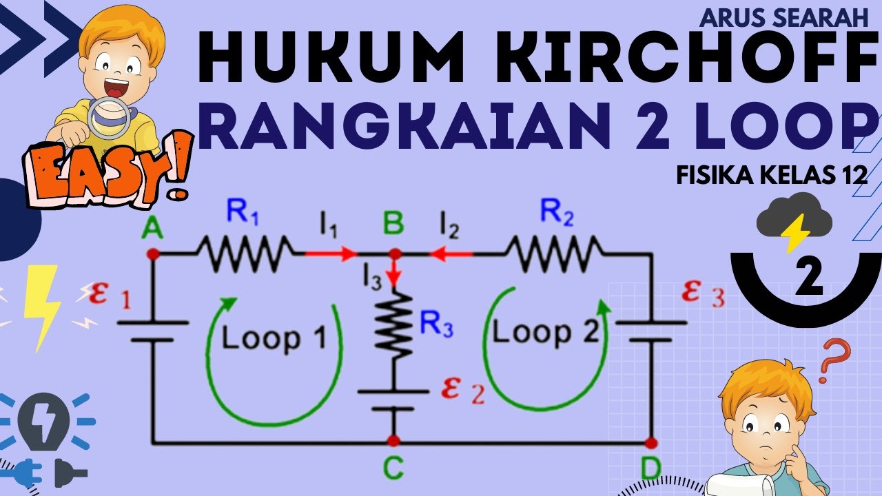
Hukum Kirchhoff Rangkaian 2 Loop : [CARA CEPAT] - Listrik Dinamis Fisika Kelas 12 Part 2

The Concept of Short Circuit

RANGKAIAN LISTRIK : Respons Alami dan Respons Steady State ( Part 25 )

Tugas 1, kapasitor sebagai penyimpan muatan listrik
5.0 / 5 (0 votes)
