Lecture 15: Booting Process
Summary
TLDRThis video explains the booting sequence of ARM Cortex-M processors, covering key steps like system reset, interrupt vector table, and the processor's behavior during boot. It details how the processor initializes the stack pointer and program counter, executes the reset handler, and identifies boot modes based on pin configurations. Additionally, the video explores memory mapping for code, bootloader, and custom bootloaders, as well as how to set up the boot mode and memory values. The content offers insights into the configuration of microcontrollers, such as STM32, and provides practical guidance for developers.
Takeaways
- 😀 System reset sets all registers to their reset values, except for the reset flags in the clock controller and backup domain registers.
- 😀 A system reset can be triggered by hardware (e.g., pressing the reset button) or software.
- 😀 The NRST pin is pulled low to initiate a system reset and is pulled up internally in the processor chip.
- 😀 The bypass capacitor on the NRST pin helps improve electromagnetic susceptibility (EMS) by removing high-frequency voltage signals.
- 😀 The interrupt vector table holds memory addresses for initializing the Main Stack Pointer (MSP) and the reset handler function.
- 😀 Upon booting, the processor first reads two pins (boot 0 and boot 1) to determine the boot mode.
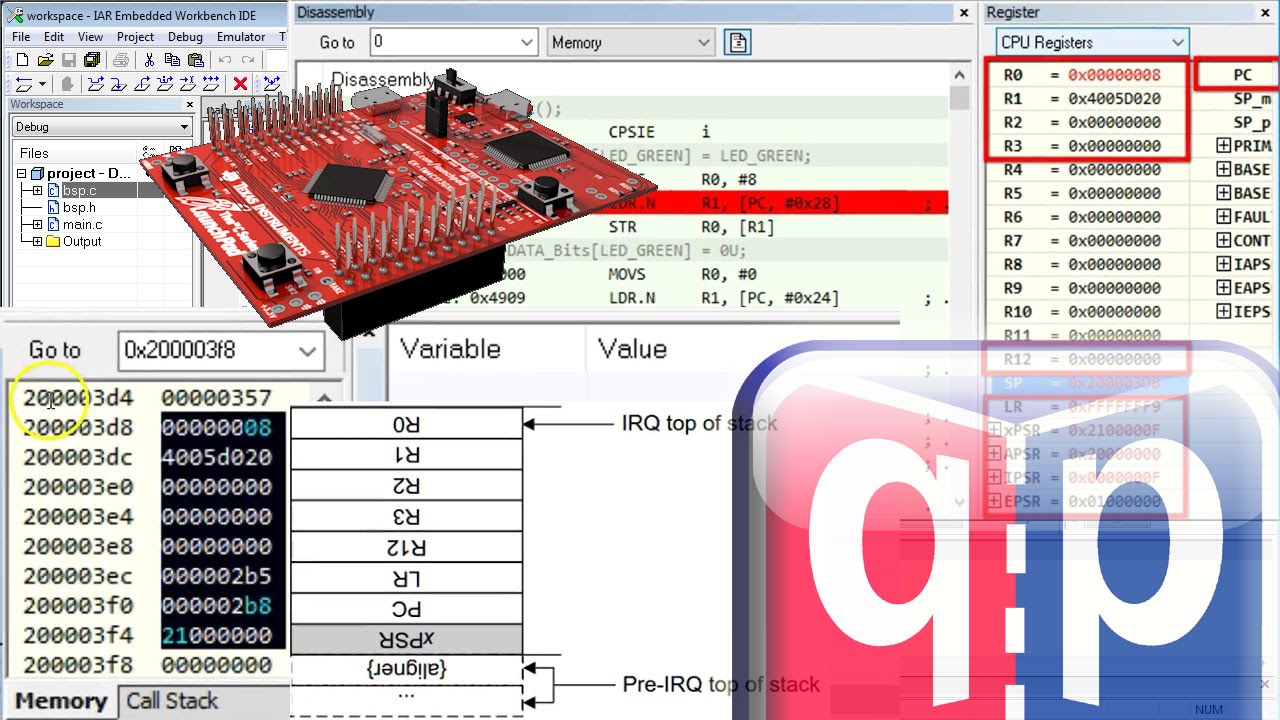
- 😀 The processor copies the value at memory address 0 to initialize the Main Stack Pointer (MSP), and the value at address 4 to the Program Counter (PC) to start executing the reset handler.
- 😀 The reset handler typically initializes hardware (e.g., data and BSS segments) before calling the main() function.
- 😀 Boot mode is determined by the voltage applied to the boot 0 and boot 1 pins, allowing the processor to boot from internal flash, system memory, or SRAM.
- 😀 The processor fetches the stack pointer and program counter from memory addresses 0 and 4, respectively, depending on the boot memory configuration (internal flash, system memory, or SRAM).
Q & A
What happens during a system reset of ARM Cortex-M processors?
-During a system reset, all registers are set to their reset values, except for the reset flags in the clock controller register (CSR) and the registers in the backup domain.
How is a system reset triggered in ARM Cortex-M processors?
-A system reset can be triggered by hardware or software. For instance, if the NRST pin is pulled low, a system reset occurs.
What role does the bypass capacitor play during the reset process?
-The bypass capacitor, added in parallel with the reset button, helps improve electromagnetic susceptibility (EMS) by filtering high-frequency voltage signals from the NRST pin, reducing transient circuit demands on the power supply.
What is electromagnetic susceptibility (EMS)?
-EMS is the ability of a device to operate without fault under electrical disturbances and noise. It measures the tolerance of a device to various forms of electromagnetic radiation.
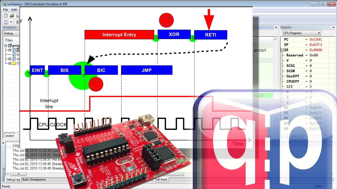
How does the ARM Cortex-M processor handle the interrupt vector table during boot?
-The processor first reads the memory address at 0, which initializes the Main Stack Pointer (MSP), and then reads the memory address at 4, which points to the reset handler function.
What happens after the ARM Cortex-M processor copies values from memory address 0 and 4 during boot?
-After copying the values from memory address 0 and 4, the processor initializes the MSP and the program counter (PC) and starts executing the reset handler function. The reset handler then performs hardware initialization and calls the main() function.
What is the significance of the least significant bit in the program counter (PC) of ARM Cortex-M processors?
-The least significant bit in the program counter indicates whether the processor runs in Thumb mode (bit set to 1) or ARM mode (bit set to 0). Since ARM Cortex-M processors support only Thumb mode, the least significant bit is always 1.
What are the different boot modes available for ARM Cortex-M processors?
-ARM Cortex-M processors support multiple boot modes: booting from internal flash memory, system memory, or internal SRAM. The boot mode is determined by the voltage on pins boot 0 and boot 1.
What is the role of a bootloader in ARM Cortex-M processors?
-A bootloader is a small program that can reside in system memory, and it is used to initialize the system. It may also upgrade the firmware in the internal flash memory, allowing firmware updates. STM32 microprocessors come with a pre-programmed bootloader in system memory.
How is the boot memory in ARM Cortex-M processors determined?
-The boot memory is determined by the voltage on boot pins boot 0 and boot 1. If boot 0 is grounded, the processor boots from internal flash memory. If boot 0 is high and boot 1 is low, the processor boots from system memory. If both pins are high, the processor boots from internal SRAM.
Outlines

Cette section est réservée aux utilisateurs payants. Améliorez votre compte pour accéder à cette section.
Améliorer maintenantMindmap

Cette section est réservée aux utilisateurs payants. Améliorez votre compte pour accéder à cette section.
Améliorer maintenantKeywords

Cette section est réservée aux utilisateurs payants. Améliorez votre compte pour accéder à cette section.
Améliorer maintenantHighlights

Cette section est réservée aux utilisateurs payants. Améliorez votre compte pour accéder à cette section.
Améliorer maintenantTranscripts

Cette section est réservée aux utilisateurs payants. Améliorez votre compte pour accéder à cette section.
Améliorer maintenantVoir Plus de Vidéos Connexes

#13 Startup Code Part-1: What is startup code and how the CPU gets from reset to main?
#17 interrupts Part-2: How most CPUs (e.g. MSP430) handle interrupts?
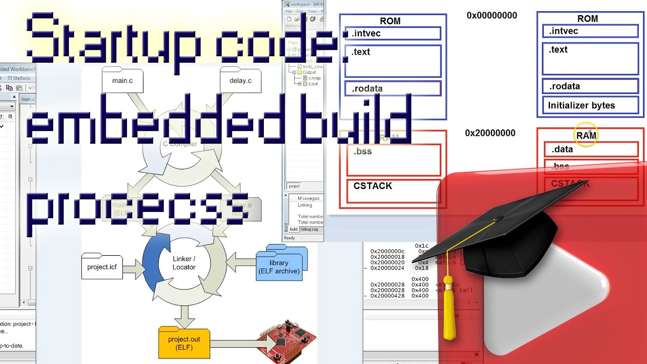
#14 Startup Code Part-2: Replacing the vector-table, embedded software build process
#18 interrupts Part-3: How interrupts work on ARM Cortex-M?

ARM Processor Programming Modes - ARM Processor - Microcontroller and Embedded Programming

How Does Linux Boot Process Work?
5.0 / 5 (0 votes)
