How to Read a Schematic
Summary
TLDRThis video script offers a beginner's guide to reading electronic schematics, explaining the use of specific symbols to represent components like batteries, resistors, switches, and LEDs. It clarifies the difference between a wiring diagram and a schematic, emphasizing the importance of understanding symbols and the representation of connections, including the use of ground symbols. The script also touches on the concept of polarized and non-polarized capacitors, and introduces a potentiometer for adjustable resistance. Viewers are directed to a webpage for more symbols and encouraged to explore related projects on the presenter's YouTube channel.
Takeaways
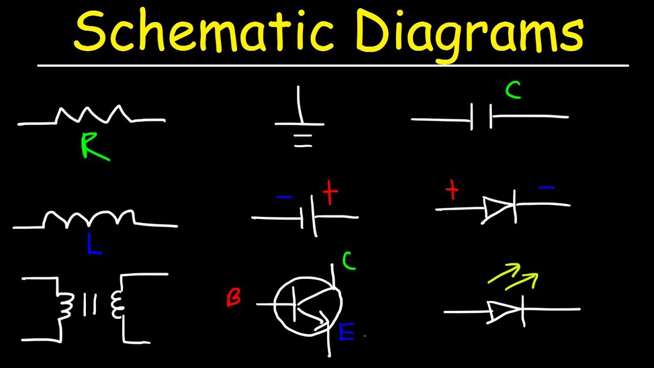
- 😀 A schematic is a diagram that uses specific symbols to represent electronic components and their connections, as opposed to a wiring diagram which uses pictures or photos of parts.
- 🔋 The symbol for a battery in a schematic is a longer line to represent the positive side, and additional lines for multiple cells.
- ⚡ The resistor is symbolized by a zigzag line in North America or a rectangle in the international standard.
- 🔑 The on/off switch is depicted as an open line when off and a different symbol when on.
- 💡 The LED symbol in a schematic includes arrows to indicate light emission, which is characteristic of a light-emitting diode.
- 🔗 Learning the symbols is crucial for understanding schematics, although there are many, only a few are commonly used.
- 🔄 Wires in a schematic can cross without connection, indicated by no dot at the intersection, or with a connection, indicated by a dot.
- 🌐 The ground symbol, representing earth ground and negative, is used to simplify wiring diagrams by connecting multiple lines to a single point.
- 🚗 Different types of grounds exist, such as chassis ground in cars, each with its unique symbol.
- ➡️ A diode allows current to flow in one direction only, with the arrow indicating the direction of conventional current flow.
- 🎚 A potentiometer, or variable resistor, is symbolized with an arrow pointing to it and is used for adjusting values, like volume in a radio.
Q & A
What is the main difference between a wiring diagram and a schematic?
-A wiring diagram is a visual representation of a circuit using pictures or photos of the parts and colored lines, while a schematic uses specific symbols to represent components and is not always laid out like the final circuit.
What does the symbol for a battery represent in a schematic?
-In a schematic, the symbol for a battery typically represents one battery cell, with multiple cells drawn together if the battery has more than one cell. The longer line indicates the positive side of the battery.
How is a resistor represented in a schematic in North America?
-In North America, a resistor is represented by a zigzag line in a schematic.
What is the international standard symbol for a resistor?
-The international standard symbol for a resistor is a rectangle.
What does the symbol for an on/off switch look like in a schematic?
-The symbol for an on/off switch in a schematic is typically drawn as a diagonal line with a gap, indicating it is open or off. If it is closed or on, the gap would be filled.
What is the symbol for an LED in a schematic and why is it designed that way?
-The symbol for an LED in a schematic is a diode symbol with arrows representing light being emitted from it. This design makes sense because LED stands for Light Emitting Diode.
How do you know if the lines in a schematic are connected or not?
-In a schematic, if lines cross without a dot at the intersection, they are not connected. If a dot is present at the intersection, it indicates that the lines are connected.
What is the purpose of the ground symbol in a schematic?
-The ground symbol in a schematic represents earth ground and is used to simplify the wiring by indicating where all the lines eventually end up, without having to draw all the lines to one ground symbol.
What is the difference between a polarized and a non-polarized capacitor in terms of their symbols in a schematic?
-A polarized capacitor, like an electrolytic capacitor, is represented by a symbol with a plus or minus sign or a stripe on one side. A non-polarized capacitor is represented by two straight lines without any signs.
What is a potentiometer and how is it symbolized in a schematic?
-A potentiometer is an adjustable resistor, used for example to adjust volume in a circuit. In a schematic, it is symbolized like a resistor with an arrow pointing to it, following the international standard of a rectangle for resistors.
What is the direction of conventional current flow in relation to the diode symbol in a schematic?
-Conventional current flow is in the direction of the arrow in the diode symbol, which is opposite to the flow of negative electrons.
Outlines

Cette section est réservée aux utilisateurs payants. Améliorez votre compte pour accéder à cette section.
Améliorer maintenantMindmap

Cette section est réservée aux utilisateurs payants. Améliorez votre compte pour accéder à cette section.
Améliorer maintenantKeywords

Cette section est réservée aux utilisateurs payants. Améliorez votre compte pour accéder à cette section.
Améliorer maintenantHighlights

Cette section est réservée aux utilisateurs payants. Améliorez votre compte pour accéder à cette section.
Améliorer maintenantTranscripts

Cette section est réservée aux utilisateurs payants. Améliorez votre compte pour accéder à cette section.
Améliorer maintenantVoir Plus de Vidéos Connexes

Belajar Cara Membaca Skema Part-2, sekali tonton harus bisa

BASIC ELECTRONIC COMPONENTS

cara membaca skema elektronika
Schematic Diagrams & Symbols, Electrical Circuits - Resistors, Capacitors, Inductors, Diodes, & LEDs

GCSE Physics - Components #19

Belajar Komponen SMD, Apa itu THT & SMT juga SMD?, Mengenal komponen SMD
5.0 / 5 (0 votes)
