Engine Fuel Systems Part 1 - Aircraft Gas Turbine Engines #19
Summary
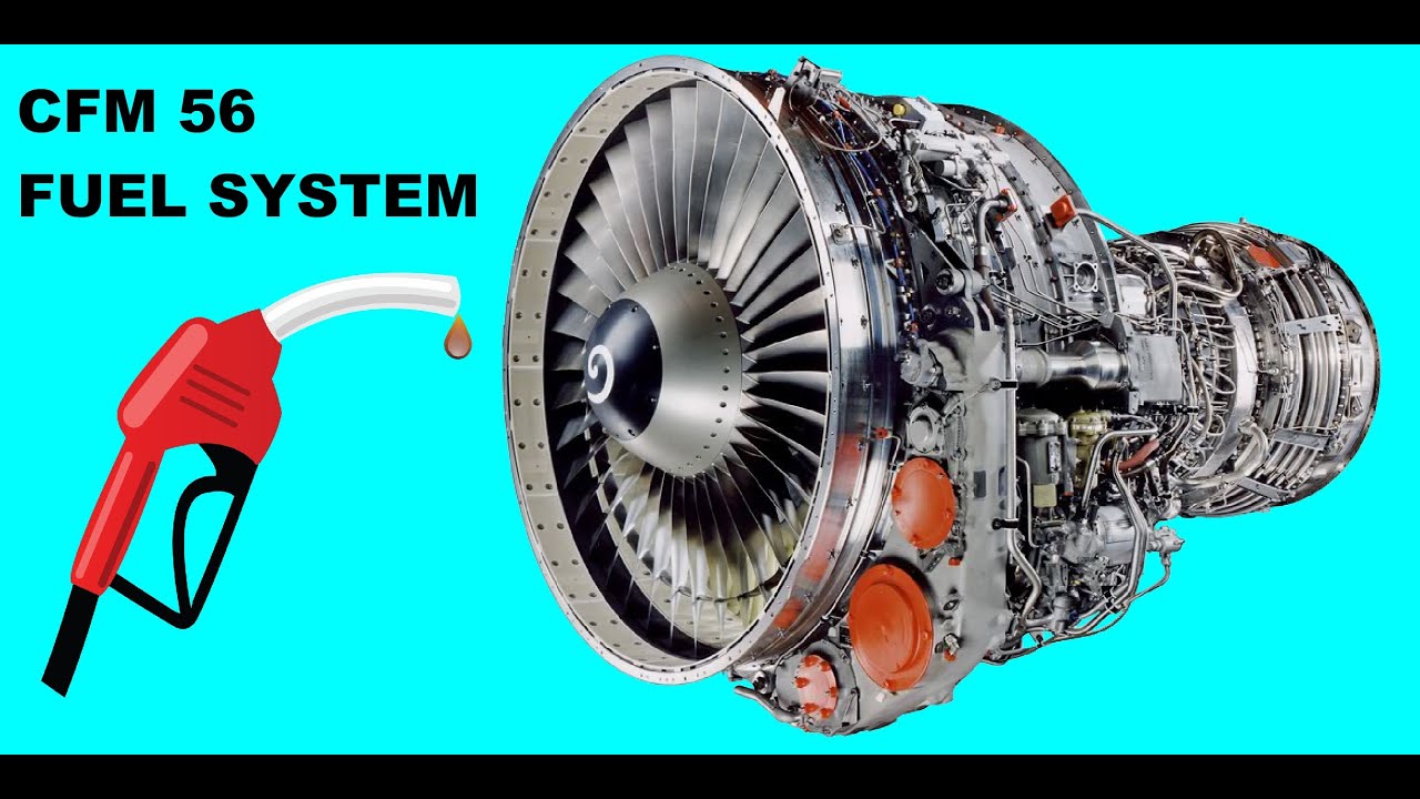
TLDRThe script delves into the engine fuel system of aircraft, detailing its components and functions. It explains how the system receives low-pressure fuel from the airframe tanks, increases pressure for combustion, and includes mechanisms like booster pumps, low-pressure fuel pumps, oil coolers, and fuel heaters to ensure efficient and safe operation. The focus is on the intricacies of the fuel control unit, which adjusts fuel flow according to various engine requirements, highlighting the importance of components like the high-pressure fuel pump and the hydro-mechanical fuel control systems.
Takeaways
- 🛩️ The engine fuel system is a critical part of the aircraft's fuel supply, receiving low-pressure fuel from the airframe fuel system and increasing it to a usable pressure for the engine.
- 🔧 The booster pumps in the wing and center tanks pass fuel to the engine through non-return valves, ensuring a continuous supply even if the engine fire control handle is activated.
- 🔄 The low-pressure fuel system can be used to shut off the fuel supply for maintenance or in case of engine fire, but it takes longer to shut down the engine compared to using high-pressure fuel.
- 🚫 The low-pressure fuel system contains a significant amount of fuel in the pipeline, which can maintain supply to the burners for some time, unlike the high-pressure system.
- 🔧 The low-pressure fuel pump, also known as the backing pump, supports the fuel supply to the engine in case of booster pump failure and helps prevent cavitation in the high-pressure pump.
- 🔥 A fuel cooled oil cooler is used in most gas turbine engines to cool the oil and heat the fuel, preventing ice crystal formation that could block the fuel system.
- 🛠️ The oil feed line to the fuel cooled oil cooler includes a pressure maintaining valve to ensure oil leaks into the fuel system rather than fuel into the oil system in case of a leak, avoiding potential hazards.
- 🌡️ The fuel heater works with the fuel cool oil cooler to maintain a predetermined fuel temperature, using a Verna therm thermal actuator sensitive to temperature changes.
- 📏 The flow meter measures the instantaneous fuel flow and can totalize the amount of fuel used, with two types in use on large jet aircraft: the vane type and the mass flow measuring type.
- 🛡️ The fuel pressure is sensed after the low-pressure fuel filter, which protects sensitive control components from dirt or contamination, and is indicated on the flight deck for monitoring.
- ⚙️ The high-pressure fuel pump, driven by the engine accessory gearbox, uses a plunger or spur gear type design to supply the necessary fuel flow, with the output controlled by a servo piston from the fuel control unit.
Q & A
What are the two main sections of the aircraft's fuel system?
-The two main sections of the aircraft's fuel system are the airframe fuel system and the engine fuel system.
What is the primary function of the engine fuel system?
-The primary function of the engine fuel system is to receive low pressure fuel supply from the aircraft fuel tanks, increase the fuel pressure to a value usable by the fuel nozzles in the combustion chamber, and control the volume of fuel into the engine to meet its requirements.
What is the role of booster pumps in the airframe fuel system?
-Booster pumps in the airframe fuel system are responsible for passing fuel through non-return valves to the engine via the low-pressure fuel supply.
How can the low-pressure fuel be used in the event of a fire or component removal?
-The low-pressure fuel can be used to shut off the supply to the engine automatically if the engine fire control handle is activated or to facilitate the removal of a fuel system component by stopping the fuel supply.
What is the purpose of the low-pressure fuel pump in the engine fuel system?
-The low-pressure fuel pump, sometimes called the backing pump, is used to back up the fuel supply to the engine in case of a failure of both booster pumps in the wing tanks and to minimize the chance of cavitation at the inlet of the high-pressure pump.
What is the function of a fuel cooled oil cooler in gas turbine engines?
-A fuel cooled oil cooler serves the dual purpose of cooling the oil and heating the fuel, which helps to eliminate the formation of ice crystals that may block components downstream in the fuel system.
How does the pressure maintaining valve in the oil feed line to the fuel cooled oil cooler work?
-The pressure maintaining valve keeps the oil pressure in the cooler higher than the fuel pressure, ensuring that if an internal leak occurs, the oil leaks into the fuel system rather than the fuel leaking into the oil system.
What is the purpose of the fuel heater in the fuel system?
-The fuel heater assists in warming the fuel to eliminate ice crystals and maintain a predetermined fuel temperature through the use of compressed bleed air.
What are the two types of flow meters used on large jet aircraft?
-The two types of flow meters used on large jet aircraft are the vane type and the mass flow measuring type.
How does the high-pressure fuel pump function in the engine fuel system?
-The high-pressure fuel pump, which can be of different types such as plunger or spur gear type, is fitted and driven by the engine accessory gearbox and is responsible for supplying fuel under high pressure to the outlet.
What are the two types of hydro-mechanical fuel control systems used in gas turbine engines?
-The two types of hydro-mechanical fuel control systems used in gas turbine engines are the pressure control system and the proportional flow control system, with the latter being more popular due to its compactness and insensitivity to flow variations downstream of the throttle.
Outlines
🛩 Engine Fuel System Mechanics
The first paragraph delves into the engine fuel system's role in managing fuel supply for aircraft engines. It explains how the system receives low-pressure fuel from the airframe's tanks and increases the pressure to meet combustion chamber requirements. Key components such as booster pumps, non-return valves, and low-pressure fuel pumps are highlighted, with a focus on their functions in maintaining fuel pressure and preventing cavitation. The paragraph also discusses the importance of the fuel cooled oil cooler in preventing ice crystal formation and the role of the fuel heater and flow meter in maintaining fuel temperature and measuring fuel flow. Additionally, it touches on the significance of the low-pressure fuel in emergency shutdowns and the use of filters to protect sensitive engine components.
📏 Types and Functions of Fuel Flow Meters
The second paragraph provides an in-depth look at the two types of fuel flow meters used in large jet aircraft: the vane type and the mass flow measuring type. The vane type, found in older systems, measures the volume of fuel flow and is described as less accurate. In contrast, the mass flow type offers greater precision, within a 1% margin of error, by measuring the mass flow rate. This type uses an impeller and drum with magnets that interact with pickup coils to translate angular displacement into a mass flow rate. The paragraph also covers the importance of fuel temperature and pressure sensing for system monitoring and the various types of high-pressure fuel pumps, including plunger and spur gear types, and their roles in the fuel control system. The hydro mechanical fuel control systems, specifically the pressure control and proportional flow control systems, are also discussed, with a focus on the latter's advantages in compactness and insensitivity to flow variations.
Mindmap
Keywords
💡Engine Fuel System
💡Booster Pumps
💡Low-Pressure Fuel
💡High-Pressure Fuel
💡Low Pressure Fuel Pump
💡Fuel Cooled Oil Cooler
💡Fuel Heater
💡Fuel Flow Meter
💡Fuel Filter
💡High-Pressure Fuel Pump
💡Fuel Control Unit
Highlights
The engine fuel system is a critical component that increases fuel pressure and controls fuel volume to meet engine requirements.
The booster pumps in the wing and center tanks pass fuel through non-return valves to the engine via the low-pressure fuel system.
Low-pressure fuel can be used to shut off the engine automatically in case of an engine fire or for maintenance purposes.
The low-pressure fuel pump, also known as the backing pump, supports the fuel supply in case of booster pump failure.
A fuel cooled oil cooler is used to prevent ice crystal formation in the fuel system, ensuring smooth operation.
The oil cooler has a pressure maintaining valve to prevent oil from leaking into the fuel system, avoiding potential hazards.
The fuel heater and fuel cool oil cooler work together to maintain a predetermined fuel temperature using compressed bleed air.
A Verna therm thermal actuator is used for automatic temperature control in the fuel system.
The pressure fuel filter protects sensitive control components from dirt and contamination.
Flow meters measure instantaneous fuel flow and can integrate total fuel usage, with two types being the vane type and mass flow measuring type.
The fuel temperature and pressure are monitored for system performance and safety.
The high-pressure fuel pump is driven by the engine accessory gearbox and is crucial for fuel flow regulation.
Plunger type pumps are used in high-pressure fuel pumps for their ability to control fuel flow based on engine demand.
Spur gear type fuel pumps offer a simpler and lighter construction compared to plunger type pumps.
The fuel control unit is central to managing fuel flow, adjusting for various engine conditions and requirements.
Hydro mechanical fuel control systems, including pressure control and proportional flow control systems, are still widely used.
The proportional flow control system is preferred for its compact design and insensitivity to flow variations downstream of the throttle.
The fuel control unit incorporates various devices to adjust fuel flow for air intake pressure, engine acceleration, and exhaust gas temperature control.
Transcripts
the entire system which stalls carries
and controls the fuel supply for the
engines can be divided into two sections
the airframe fuel system
at the engine fuel system
here we'll look specifically at the
engine fuel system which receives the
low pressure fuel supply from the
aircraft fuel tanks which are part of
the airframe fuel system
the engine fuel system increases the
fuel pressure to a value that the fuel
nozzles in the combustion chamber can
use
and then controls a volume of fuel into
the engine so that it conforms to the
engine's requirements
the engine fuel system consists of a
number of components which will now
describe in more detail
the booster pumps which are situated in
the wing and center tanks of the
airframe fuel system pass fuel through
non-return valves to the engine via the
low pressure fuel
the low-pressure fuel is
electrically operated it can be shut
automatically if the engine fire control
handle is activated
if a component of the fuel system needs
to be removed for whatever purposes the
low-pressure fuel can be used to
shut off the supply of fuel to the
engine to facilitate the removal
if the high-pressure fuel cannot be
used to shut down the engine for
whatever reason as an alternative the
low-pressure fuel can be used to
stop the engine however using the
low-pressure fuel to shut down the
engine instead of the high-pressure fuel
will mean that the engine will take
much longer to shut down this is because
the pipeline between the low pressure
fuel and the engine contains a
considerable amount of fuel which will
maintain the supply to the burners for
some time whereas in the case of the
high pressure fuel very little fuel
is contained in the pipeline between
aids and the combustion chambers
after it's passed through the low
pressure fuel cocked the fuel then
enters the engine fuel system and is
delivered to the low pressure fuel pump
the low pressure fuel pump is sometimes
called the backing pump because it will
attempt to back up the fuel supply to
the engine in the event of failure of
both of the booster pumps in the wing
tanks
pressure fuel pump is used to supply
positive fuel pressure directly to the
high-pressure pump by maintaining a
positive pressure the low pressure pump
minimizes the chance of cavitation
occurring at the inlet of a
high-pressure pump
the low pressure fuel pump is driven by
the engines accessory gearbox which
itself is driven by the high pressure
compressor shaft
a fuel cooled oil cooler is fitted in
the majority of gas turbine engine
installations the oil cooler serves the
double purpose of cooling the oil and
also heating the fuel
by raising the temperature of the fuel
the oil cooler eliminates the formation
of ice crystals which may block
components downstream in the fuel system
the oil feed line to the fuel cooled oil
cooler incorporates a pressure
maintaining valve this valve keeps the
oil pressure in the cooler higher than
the fuel pressure if the oil cooler does
develop an internal leak then the fact
that the oil pressure is higher than the
fuel pressure will ensure that the oil
leaks into the fuel system rather than
the fuel leaking into the oil system
which could be very dangerous
the fuel heater assists in the warming
of the fuel and thus the elimination of
ice crystals the fuel heater working in
conjunction with the fuel cool oil
cooler uses compressed breed air to warm
the fuel to automatically maintain a
predetermined fuel temperature
the automatic temperature control can be
achieved by the action of a Verna therm
thermal actuator the thermal actuator
incorporates a material which is
sensitive to temperature change this is
used to open or close a valve which
regulates the entry of hot air into the
fuel heater from the engine compressor
pressure fuel filter is the first line
of defense protecting the delicate
control components within the high
pressure fuel pump and the fuel control
unit from the effects of dirt or
contamination
the low-pressure filter is usually a
replaceable paper filter element which
is capable of filtering out particles
larger than 50 to 100 microns
the flow meter measures the
instantaneous fuel flow in gallons per
hour kilograms per hour or pounds per
hour the flow meter may also include an
integrating system which can add the
total amount of fuel used
are basically two types of flow meter in
use on large jet aircraft they are the
vane type and the mass flow measuring
type
the vein type of fuel flow meter which
is fitted to older aircraft systems is
designed to measure volume of flow
the flowmeter consists of a vein which
is moved against the force of a
restraining spring by the volume of fuel
flowing past it this system is not too
accurate
the mass flow type of instrument can be
accurate to within plus or minus 1% fuel
flowing through the instrument rotates
both the drum and a spring mounted
impeller which have magnets fixed to
them
sense by pickup coils which translate
the difference in angular displacement
between the magnets into a mass flow
rate
you
the fuel temperature is sensed as the
fuel leaves of your heater
fuel temperature is indicated on the
flight deck to allow system monitoring
you
the fuel pressure is sensed as the fuel
leaves the low-pressure fuel filter
fuel no pressure may be indicated by
either an LP fuel warning light all the
activation of warnings on the eye cash
or ECAM depending on aircraft type
you
a high pressure fuel pump is fitted to
and driven by the engine accessory
gearbox the engine accessory gearbox
itself is driven by the high-pressure
compressor shaft
I pressure fuel pump Illustrated is
representative of one type of pump
employed its a plunger type pump it can
be used as a single unit if the volume
of fuel required is not too great but in
larger engines two units can be driven
together to supply a greater fuel flow
several plungers are fitted on a rotor
assembly
against a stationary camp late which
causes them to reciprocate within the
balls that contain them on the rotor
assembly
the distance that the plungers move
during this reciprocating action is
dictated by the angle of inclination of
the cam plate here we see the camp eight
angled so that the plungers stay in the
same position in their balls as the
rotor drives them round
now the camp blade angle is such that
the springs force the plungers to their
maximum stroke when they are at the top
of the cam plate sucking fuel into the
pores
and the kemplay forces the plungers to
their minimum stroke when they are at
the bottom of the cam plate forcing fuel
under pressure to the outlet of the pump
the angle of inclination of the camp
rate is controlled by a servo piston
which itself is controlled from the fuel
control unit
systems incorporate a fuel filter into
the output of the high pressure fuel
pump to prevent very fine particles
entering the extremely small passageways
inside the fuel control unit the fuel
filter is composed of a number of wire
mesh green disks
the spur gear type fuel pump is simpler
and lighter in construction and the
plunger type fuel pump and like the
plunger type pump the spur gear type
pump is driven by the accessory gearbox
the output of the spur gear type pump is
directly proportional to its rotational
speed
the fuel control unit controls the fuel
flow to the
for every thrust setting
there are two types of hydro mechanical
fuel control systems still used on gas
turbine engines they are the pressure
control system and the proportional flow
control system the proportional flow
control system is the more popular of
the two types because it is more compact
than the pressure control system and
it's not sensitive to the effect of flow
variations that occur downstream of the
throttle
the proportional flow control system is
the type we'll use to describe the
individual parts of a fuel control unit
various devices within the fuel control
unit are used to adjust the fuel flow to
cater for variations in air intake
pressure engine acceleration control
exhaust gas temperature rpm limiting and
compress the delivery pressure
Ver Más Videos Relacionados
Engine Fuel Systems Part 2 - Aircraft Gas Turbine Engines #20
Fuel Distribution - Fuel Systems - Airframes & Aircraft Systems #66
How does the AIRBUS FUEL SYSTEM work? Explained by CAPTAIN JOE
Combustion Chambers Part 2 - Aircraft Gas Turbine Engines #09
Fuel Types - Fuel Systems - Airframes & Aircraft Systems #64
Lubrication Part 2 - Aircraft Gas Turbine Engines #23
5.0 / 5 (0 votes)