L39 | Emitter Coupled Logic | Digital System Design (KEC302) | Hindi
Summary
TLDRThis video lecture covers the essentials of digital system design, focusing on TTL (Transistor-Transistor Logic) circuits. The lecturer explains the construction, working, and advantages of TTL, with a focus on differential amplifiers and meter logic circuits. Key concepts like speed, transistor behavior in active and cutoff modes, and complementary outputs are discussed. The lecture also compares TTL logic with other logic families, highlighting its high-speed performance and power dissipation challenges. A comprehensive look at TTL's operation, including its applications and limitations, makes this lecture an essential resource for digital logic enthusiasts.
Takeaways
- 😀 TTL logic circuits work faster because transistors never enter saturation mode, eliminating storage time.
- 😀 The main advantage of meter-capacitor logic circuits is their high-speed operation due to the differential amplifier configuration.
- 😀 TTL logic operates in active and cutoff regions, where transistors alternate between being on and off, ensuring faster performance.
- 😀 Bipolar TTL logic circuits have high-speed performance compared to other families due to their active and cutoff behavior.
- 😀 Differential amplifiers in TTL circuits have complementary outputs, meaning when one transistor is active, the other is in cutoff.
- 😀 The primary disadvantage of TTL circuits is higher power consumption compared to other logic families.
- 😀 Meter-capacitor logic circuits eliminate storage time by preventing transistors from going into saturation, enhancing speed.
- 😀 The working principle of TTL circuits ensures that output voltage levels are highly responsive to input changes, making them fast.
- 😀 The use of reference voltages in TTL circuits ensures that transistors remain in active or cutoff states, contributing to high-speed performance.
- 😀 The design of TTL logic circuits allows them to be ideal for applications where speed is a critical factor, like in digital systems.
Q & A
What is the main focus of the video lecture on Digital System Design?
-The main focus of the lecture is on Transistor-Transistor Logic (TTL) circuits, the different logic families, and their operations, with a special emphasis on 'Meter Cupra' logic circuits and their high-speed performance.
What are the two types of logic families discussed in the script?
-The two types of logic families discussed are bipolar and unipolar logic families. These families differ in their voltage behavior and power dissipation.
Why are TTL circuits considered high-speed circuits?
-TTL circuits are considered high-speed because their transistors never enter saturation mode, which eliminates storage time and allows for faster switching between active and cutoff states.
What is the advantage of not having storage time in TTL circuits?
-The absence of storage time in TTL circuits means faster processing, as there is no delay due to charge accumulation in the transistors. This is crucial for achieving high-speed operation.
How does a differential amplifier work in the TTL circuit?
-In a differential amplifier used in TTL circuits, one transistor operates in an active region while the other remains in cutoff. The output is complementary, with one output being high when the other is low.
What role does the 'Meter Cupra' logic family play in TTL circuits?
-'Meter Cupra' logic family plays a significant role in achieving high speed in TTL circuits. It works by using a differential amplifier configuration that keeps the transistor either in active or cutoff state, ensuring fast switching.
What is the main disadvantage of the TTL logic family mentioned in the script?
-The main disadvantage of the TTL logic family is its higher power dissipation and cost. The high-speed performance comes with an increase in power consumption compared to other logic families.
What does 'cutoff' and 'active' mean in the context of transistor operation?
-In transistor operation, 'cutoff' refers to the state where the transistor is off and no current flows, while 'active' means the transistor is on, allowing current to flow and enabling the logic operation.
What is the effect of applying low voltage to a TTL transistor circuit?
-When low voltage is applied to a TTL transistor circuit, the transistor enters the cutoff region, and the output current becomes zero. This leads to a drop in the output voltage, typically resulting in a low output state.
Why does the 'unipolar logic family' improve power dissipation?
-The unipolar logic family is designed to reduce power dissipation by using a single polarity (either positive or negative) for the logic operations. This improves efficiency by minimizing unnecessary power loss during switching.
Outlines

Esta sección está disponible solo para usuarios con suscripción. Por favor, mejora tu plan para acceder a esta parte.
Mejorar ahoraMindmap

Esta sección está disponible solo para usuarios con suscripción. Por favor, mejora tu plan para acceder a esta parte.
Mejorar ahoraKeywords

Esta sección está disponible solo para usuarios con suscripción. Por favor, mejora tu plan para acceder a esta parte.
Mejorar ahoraHighlights

Esta sección está disponible solo para usuarios con suscripción. Por favor, mejora tu plan para acceder a esta parte.
Mejorar ahoraTranscripts

Esta sección está disponible solo para usuarios con suscripción. Por favor, mejora tu plan para acceder a esta parte.
Mejorar ahoraVer Más Videos Relacionados

8-Bit Adder built from 152 Transistors

Transistor Characteristics (CE Transistor) Basic Electronics (BJT) BE/Btech 1st year| in हिन्दी
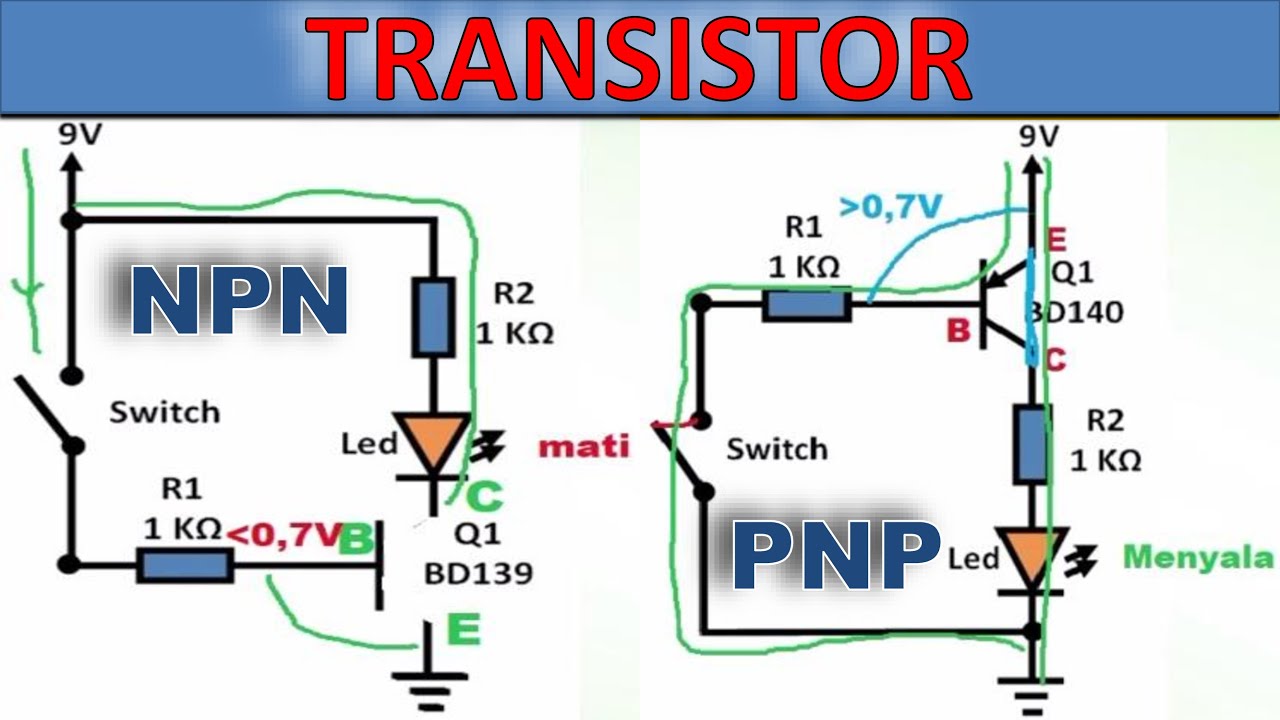
Penjelasan Transistor NPN dan PNP – Beserta contoh rangkaiannya

Constant Current Source with BJT Transistor

Making logic gates from transistors
Pertemuan 1 - Mata Kuliah Rangkaian Digital- TA 25/26 Ganjil - UNUSIDA
5.0 / 5 (0 votes)
