How To Design Automatic Voltage Regulator (AVR) Model of Power System in MATLAB/SIMULINK Software ?
Summary
TLDRIn this MATLAB tutorial, the speaker demonstrates how to design an Automatic Voltage Regulator (AVR) model for a thermal/hydro power plant using transfer functions in MATLAB/Simulink. The tutorial covers building the model step-by-step, including the use of key components such as amplifiers, exciters, generators, sensors, and a PID controller to stabilize terminal voltage. The speaker also discusses how to convert the simulated terminal voltage into actual volts and suggests various research ideas for further improvement, including the use of intelligent controllers and optimization techniques. Future tutorials will explore combining this model with load frequency control for a more comprehensive power system simulation.
Takeaways
- 😀 Introduction to the tutorial on designing an Automatic Voltage Regulator (AVR) Model of a Thermal/Hydro Power Plant using Transfer Functions in MATLAB/Simulink.
- 😀 The example used for the design is based on data from 'Power System Analysis' by Hadi Sadat, specifically Chapter 12, Example 12.6 and 12.8.
- 😀 The design involves modeling equipment in the power plant like amplifiers, exciters, sensors, and generators using transfer functions.
- 😀 The Simulink model requires transfer function blocks, gain blocks, sum blocks, and a step input function to simulate the system.
- 😀 The initial configuration for the step input block involves a reference voltage of 1 per unit with a step time of 20 seconds.
- 😀 The transfer function blocks for the amplifier, exciter, and generator are set with their respective time constants: 0.1 for amplifier, 0.4 for exciter, and 1.0 for generator.
- 😀 A scope is added to visualize the terminal voltage, which initially shows oscillations and a value lower than the required 1 per unit.
- 😀 The system is improved by adding a PID controller, which is tuned using trial-and-error with values P = 1, I = 0.25, and D = 0.28 to stabilize the terminal voltage.
- 😀 To convert the terminal voltage to actual voltage in kV, a gain block is added with a factor of 11,000, representing the 11 kV base voltage of the generator.
- 😀 The tutorial concludes with suggestions for research topics, including tuning PID controllers using advanced methods like fuzzy logic, neural networks, and optimization techniques, and integrating the AVR model with load frequency control for a comprehensive power system simulation.
Q & A
What is the purpose of the tutorial?
-The purpose of the tutorial is to teach how to design an Automatic Voltage Regulator (AVR) model for a thermal or hydro power plant using transfer functions in MATLAB/Simulink.
Which textbook is referenced in the tutorial?
-The tutorial references the book 'Power System Analysis' by Hadi Sadat, specifically chapters 12.6 and 12.8.
What are the main components used in the AVR model design?
-The main components in the AVR model are the amplifier, exciter, generator, sensor, and PID controller, each represented by transfer functions in Simulink.
What are the values for the amplifier gain and time constant?
-The amplifier gain is 10, and the time constant for the amplifier is 0.1 as per the example data.
How does the voltage response behave in the initial simulation without the PID controller?
-Without the PID controller, the terminal voltage does not reach the desired 1.0 per unit and exhibits an oscillatory response with a high overshoot.
What is the role of the PID controller in the AVR system?
-The PID controller is used to restore the terminal voltage to 1 per unit by adjusting the proportional, integral, and derivative gains, which helps reduce oscillations and overshoot in the voltage response.
What PID controller settings were used for the simulation?
-The PID controller settings used were P = 1, I = 0.25, and D = 0.28 to achieve satisfactory voltage regulation.
How is the terminal voltage converted from per unit to actual volts?
-To convert from per unit to actual volts, the per unit result is multiplied by the base voltage, which is set to 11 kV in this example. A gain block with a value of 11000 is used for this conversion.
What are some research topics suggested for further study based on this model?
-Some suggested research topics include automatic voltage control using PID controller tuning with Bode plot, Fuzzy Logic, Artificial Neural Networks, Radial Basis Function Neural Networks, and optimization techniques like Particle Swarm Optimization and Ant Colony Optimization.
How can the AVR model be expanded to reflect more real-world parameters?
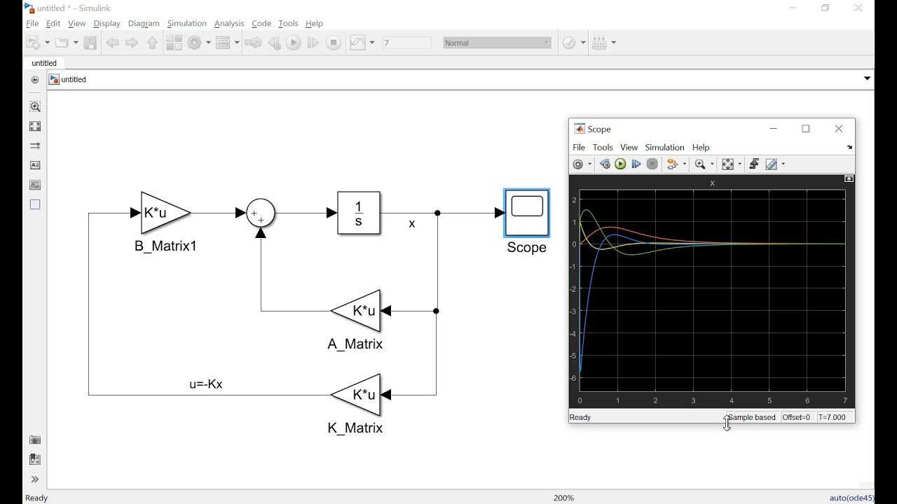
-The AVR model can be expanded by combining it with other models like Load Frequency Control or Automatic Generation Control, which would allow for the consideration of parameters such as frequency, power, and voltage variations due to sudden load changes.
Outlines

Esta sección está disponible solo para usuarios con suscripción. Por favor, mejora tu plan para acceder a esta parte.
Mejorar ahoraMindmap

Esta sección está disponible solo para usuarios con suscripción. Por favor, mejora tu plan para acceder a esta parte.
Mejorar ahoraKeywords

Esta sección está disponible solo para usuarios con suscripción. Por favor, mejora tu plan para acceder a esta parte.
Mejorar ahoraHighlights

Esta sección está disponible solo para usuarios con suscripción. Por favor, mejora tu plan para acceder a esta parte.
Mejorar ahoraTranscripts

Esta sección está disponible solo para usuarios con suscripción. Por favor, mejora tu plan para acceder a esta parte.
Mejorar ahoraVer Más Videos Relacionados

How To Implement Fuzzy Logic Control in MATLAB/SIMULINK ? (Part-3) | Dr. J. A. Laghari
Multivariable Closed Loop Control. Identification, Decoupled Control and MIMO Control with Router
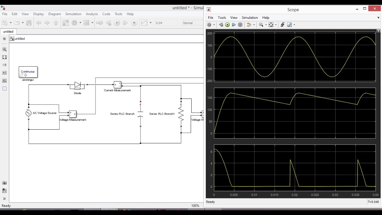
Half Wave Unctrolled Rectifier with C filter Matlab Simulink

Simulation of a Dual Active Bridge Converter in MATLAB | SIMULINK
How to Design Load Frequency Control using Simulink ? | Dr. J. A. Laghari
How to Make Simulation of Inverted Pendulum (Balancing Robot) Control in Simulink Matlab
5.0 / 5 (0 votes)
