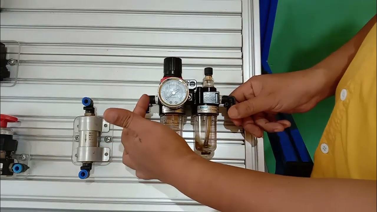
STARTING AIR SYSTEM|HOW STARTING AIR IS ADMITTED IN CYLINDER UNIT| WHAT IS SLOW TURNING VALVE|
Summary
TLDRThis video explains the operation of a marine engine's air starting system, outlining key components such as compressors, air receivers, and starting valves. The process begins with compressed air stored in a receiver and distributed through various valves to activate the engine. It highlights the role of turning gears, distributor cams, and air starting valves in ensuring smooth engine startup. Additionally, the video covers the slow turning valve for engine rotation in idle conditions and emphasizes the importance of oil separators. This informative guide is perfect for understanding the essential steps in starting a marine engine.
Takeaways
- 😀 The air starting system in marine engineering is essential for initiating engine operation, using compressed air to start the engine cylinders.
- 😀 The system includes a two-stage compressor, a receiver, and non-return valves to manage the compressed air flow.
- 😀 The air passes through various valves, such as the master shut valve and slow turning valve, before reaching the starting control valve.
- 😀 The starting control valve checks if the turning gear is engaged or disengaged before allowing the starting signal to proceed.
- 😀 Once the turning gear is disengaged, the starting air is directed to the manifold, which distributes it to each cylinder's air starting valve.
- 😀 A distributor with a negative cam controls the sequence in which the cylinders are activated by directing air to each unit's starting valve.
- 😀 The air acts on the piston in the air starting valve, unbalancing the system to open the valve and allow compressed air to enter the cylinders.
- 😀 The air starting system not only initiates engine operation but also serves other functions, such as operating the engine control systems.
- 😀 Safety features, like relief valves and oil separators, ensure that the air pressure is regulated and any oil carryover from the compressor is removed.
- 😀 The slow turning valve is used to rotate the engine at low RPM when it has been idle for a long time, preventing any internal seizing in the engine.
- 😀 The air starting system operates at 30 bar pressure, ensuring enough force to start large marine engines efficiently and safely.
Q & A
What is the purpose of the starting air system in a marine engine?
-The starting air system provides the compressed air necessary to start the marine engine. It helps in rotating the engine at the initial stage to enable ignition and operation.
How does the turning gear interlock function in the starting air system?
-The turning gear interlock ensures that the engine is not started unless the turning gear is disengaged. If the turning gear is engaged, it stops the starting signal, preventing damage to the system.
What happens when the turning gear is disengaged?
-When the turning gear is disengaged, the starting signal passes through to the distributor and master starting valve, allowing compressed air to flow into the manifold and eventually to the cylinders for engine starting.
What role does the distributor cam play in the starting air system?
-The distributor cam, which is a negative cam, controls the timing of the airflow to each cylinder. It ensures that only the correct pilot valves are activated, allowing air to pass through the manifold and into the cylinders.
Why is the starting air valve described as a balanced unit?
-The starting air valve is a balanced unit because it remains in a stable position until the starting signal is given. Once the signal is received, the valve unbalances, allowing compressed air to flow into the cylinder.
What is the purpose of the oil separator in the air starting system?
-The oil separator is used to remove any oil that may carry over from the compression stages. This prevents oil from contaminating the compressed air, which could interfere with engine performance and reliability.
What happens when air is directed to the manifold in the starting air system?
-When air reaches the manifold, it is distributed to the starting air valves of each cylinder. These valves are then activated by the air pressure to allow the air to enter the cylinders and start the engine.
What is the purpose of the slow-turning valve in the system?
-The slow-turning valve is used to rotate the engine slowly at a low RPM when the engine has been idle for a period of time. This ensures that there is no stagnation in the system and prevents damage.
What does the air compression process involve in the starting air system?
-The air is compressed in stages, stored in a receiver, and then routed through various systems such as the oil separator, relief valves, and air starting manifold. This ensures that the air is clean, pressurized, and ready for engine starting.
What are the safety features shown in the schematic diagram of the air starting system?
-The safety features include the relief valve, high-temperature cut-off valve, and pressure relief valves, all of which protect the system from overpressure and temperature-related issues, ensuring safe and reliable operation.
Outlines

Esta sección está disponible solo para usuarios con suscripción. Por favor, mejora tu plan para acceder a esta parte.
Mejorar ahoraMindmap

Esta sección está disponible solo para usuarios con suscripción. Por favor, mejora tu plan para acceder a esta parte.
Mejorar ahoraKeywords

Esta sección está disponible solo para usuarios con suscripción. Por favor, mejora tu plan para acceder a esta parte.
Mejorar ahoraHighlights

Esta sección está disponible solo para usuarios con suscripción. Por favor, mejora tu plan para acceder a esta parte.
Mejorar ahoraTranscripts

Esta sección está disponible solo para usuarios con suscripción. Por favor, mejora tu plan para acceder a esta parte.
Mejorar ahora5.0 / 5 (0 votes)


