Activity Diagram - Step by Step Guide with Example
Summary
TLDRThis video tutorial from Master2Teach introduces viewers to UML's Activity Diagram, a dynamic system representation showing control flow among activities. It explains the diagram's purpose, distinguishes it from a flowchart, and outlines its key notations, including start and end nodes, activities, control flow, and decision symbols. The tutorial also illustrates these concepts with a library system case study, guiding learners to understand and draw activity diagrams step by step.
Takeaways
- 📚 The Activity Diagram is an essential UML diagram that provides a dynamic view of a system, showing the flow of control among activities.
- 🔍 It is used to represent the operation of a system in a diagrammatic form, illustrating the control flow from one operation to another.
- 📈 Unlike the use case, communication, sequence, and class diagrams, the activity diagram focuses on the flow of activities rather than the flow of messages between objects.
- 🎯 The flow of operation in an activity diagram can be sequential, branched, or concurrent, reflecting the different ways activities can be executed.
- 📍 Start Node: The initial state before an activity begins is represented by a small filled circle in the activity diagram.
- 🏁 Final Activity Node: The end state of an activity is symbolized by a black circle with a border, resembling a selected radio button.
- 🛠 Activity: Basic building blocks of the diagram, represented by ovals or round-edged rectangles, with a short description of the activity.
- ➡️ Control Flow: Shown as a solid line with an arrow indicating the direction of the flow of activities.
- 🔄 Fork and Join: Fork splits an activity into concurrent activities, while Join combines them back into a single flow.
- 🔑 Decision Symbol: Represented by a diamond shape, it shows the point where the flow of activities can split based on conditions.
- 🔄 Merge Node: Similar to Join, it merges two activities with a condition, allowing only one activity to flow forward.
- 🔚 Final Flow Node: Indicates the end of a specific process flow, distinct from the Final Activity Node which denotes the end of all control flows.
- 🏢 Partition: Also known as swim lanes, used to group actions performed by different actors within a single thread of the diagram.
- 📝 Note or Comment: Used to add relevant comments to elements, represented by a folded symbol in the diagram.
Q & A
What is the purpose of an Activity Diagram in UML?
-The purpose of an Activity Diagram in UML is to provide a dynamic view of the system by showing the flow of control among the activities in a system. It represents the flow of operations in a diagrammatical form.
How does an Activity Diagram differ from a flowchart?
-Although Activity Diagrams may look similar to flowcharts, they are not the same. Activity Diagrams focus on the flow of activities within a system, while flowcharts generally represent a sequence of operations or processes.
What is the notation used to represent the start of an activity in an Activity Diagram?
-The start of an activity is represented by a small black filled circle, which is the standard notation for the initial state before an activity takes place.
What symbol is used to denote the end state of an activity in an Activity Diagram?
-The end state of an activity is denoted by a black circle that resembles a selected radio button.
How are activities represented in an Activity Diagram?
-Activities in an Activity Diagram are represented by oval shapes or round-edged rectangle boxes, usually containing a short description of the activity they represent.
What does a solid line with an arrow in an Activity Diagram signify?
-A solid line with an arrow in an Activity Diagram signifies the control flow, indicating the direction in which the activities progress.
Can you explain the role of a Fork in an Activity Diagram?
-A Fork in an Activity Diagram splits a single activity flow into two concurrent activities, allowing them to be performed simultaneously.
What is the purpose of a Decision Symbol in an Activity Diagram?
-The Decision Symbol, represented by a diamond shape, is used to show where the flow of activities can split into multiple mutually exclusive paths based on certain conditions.
How does a Merge Node differ from a Join in an Activity Diagram?
-A Merge Node is similar to a Join in that it combines two activities, but unlike a Join, which combines two concurrent activities back into a single flow, a Merge Node merges activities with a specific condition, allowing only one activity to flow forward.
What is the significance of a Partition in an Activity Diagram?
-A Partition, also known as swim lanes, is used in an Activity Diagram to represent or group actions carried out by different actors within a single thread.
What is the role of a Note or Comment in an Activity Diagram?
-A Note or Comment in an Activity Diagram is used to add relevant comments or information to elements, represented by a symbol with one corner folded, providing additional context or clarification.
Can you provide an example of how an Activity Diagram is used in a real-world scenario?
-In the provided script, an example of a library system is given where the Activity Diagram is used to represent the process of borrowing a book, including steps like logging in, registering, checking for book returns, processing fines, searching for books, and issuing the book.
Outlines

Dieser Bereich ist nur für Premium-Benutzer verfügbar. Bitte führen Sie ein Upgrade durch, um auf diesen Abschnitt zuzugreifen.
Upgrade durchführenMindmap

Dieser Bereich ist nur für Premium-Benutzer verfügbar. Bitte führen Sie ein Upgrade durch, um auf diesen Abschnitt zuzugreifen.
Upgrade durchführenKeywords

Dieser Bereich ist nur für Premium-Benutzer verfügbar. Bitte führen Sie ein Upgrade durch, um auf diesen Abschnitt zuzugreifen.
Upgrade durchführenHighlights

Dieser Bereich ist nur für Premium-Benutzer verfügbar. Bitte führen Sie ein Upgrade durch, um auf diesen Abschnitt zuzugreifen.
Upgrade durchführenTranscripts

Dieser Bereich ist nur für Premium-Benutzer verfügbar. Bitte führen Sie ein Upgrade durch, um auf diesen Abschnitt zuzugreifen.
Upgrade durchführenWeitere ähnliche Videos ansehen

Use Case Diagram - Step by Step Tutorial with Example
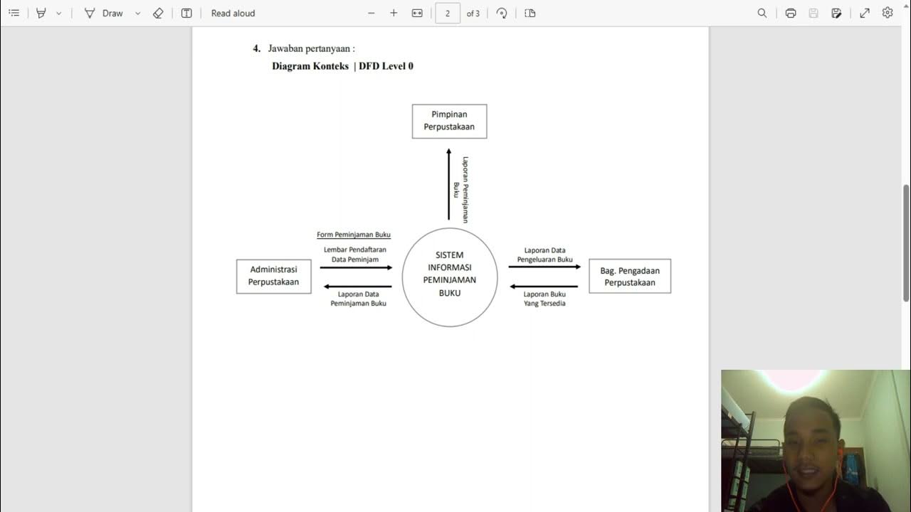
Diagram Konteks | DFD Level 0 dan DFD Level 1 | Sistem Informasi Peminjaman Buku
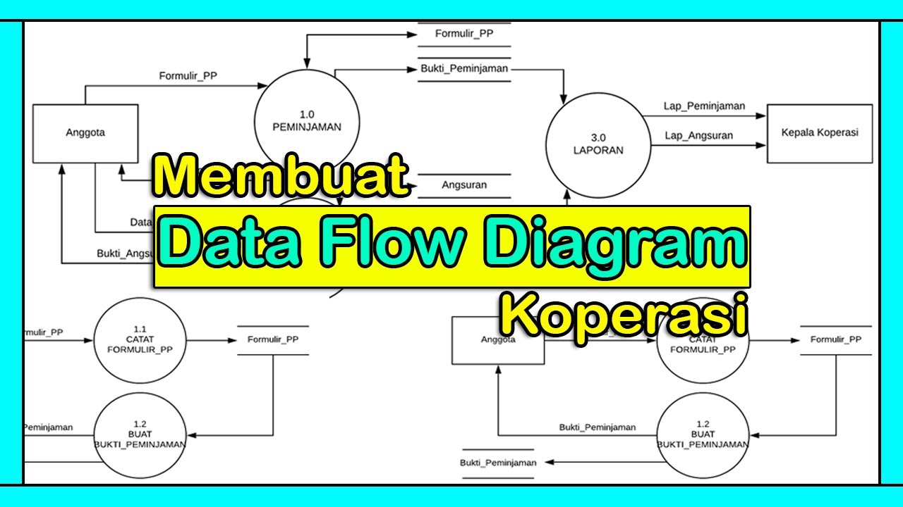
Tutorial Membuat DFD (Data Flow Diagram) | Studi Kasus Koperasi

Ladder Diagram Traffic Light Simpang 3 dengan Software CX-Programmer

5 Langkah Awal dalam Penerapan HACCP

Bilangan Kompleks • Part 3: Definisi dan Menyatakan Bentuk Bilangan Kompleks
5.0 / 5 (0 votes)
