Multiplexer
Summary
TLDRIn this video, the presenter discusses multiplexers, specifically focusing on 4-input multiplexers. The explanation covers the basics of what a multiplexer is, how it functions as a data selector, and how it uses selection lines to choose one input from many. A 4-input multiplexer circuit is demonstrated with a truth table and boolean equations. The video also highlights the use of inverters and logic gates to manage selection lines and inputs. Overall, it provides a clear and detailed explanation of how multiplexers work in digital circuits, making it accessible for beginners.
Takeaways
- 😀 A multiplexer is a combinational circuit that selects one of many inputs to output.
- 😀 The multiplexer is also known as a data selector, which allows selecting data from multiple inputs.
- 😀 A 4-to-1 multiplexer has 4 input lines (I0 to I3) and uses 2 selection lines (S0 and S1) to determine the output.
- 😀 The number of selection lines in a multiplexer is determined by the formula 2^n, where n is the number of selection lines.
- 😀 The output of the multiplexer is determined by the binary values of the selection lines.
- 😀 A truth table for multiplexers outlines all possible input-output combinations based on the selection lines.
- 😀 For a 4-to-1 multiplexer, the selection lines (S0, S1) can have 4 combinations, corresponding to the 4 inputs.
- 😀 Multiplexers are widely used as data selectors to route the correct data from several inputs to one output.
- 😀 Boolean functions can be used to represent the output of a multiplexer, depending on the values of the selection lines.
- 😀 A circuit diagram for a multiplexer can be designed using gates such as AND, OR, and NOT, as well as using inverters to complement selection lines.
Q & A
What is a multiplexer?
-A multiplexer is a combinational circuit that selects one of many inputs and forwards it to a single output line. It is also known as a data selector.
What is the function of a multiplexer?
-The function of a multiplexer is to select one input from many and pass it to the output based on the values of selection lines.
How many inputs and outputs does a 4-to-1 multiplexer have?
-A 4-to-1 multiplexer has 4 data inputs and 1 output.
What are the selection lines in a 4-to-1 multiplexer?
-In a 4-to-1 multiplexer, there are 2 selection lines, typically labeled S0 and S1, which determine which input is passed to the output.
How does a multiplexer select an input?
-A multiplexer selects an input based on the binary combination of the selection lines. For a 4-to-1 multiplexer, the selection lines (S0 and S1) can have four combinations (00, 01, 10, 11), each corresponding to one of the four inputs.
What is the truth table for a 4-to-1 multiplexer?
-The truth table for a 4-to-1 multiplexer is as follows: | S1 | S0 | Output Y | |----|----|----------| | 0 | 0 | I0 | | 0 | 1 | I1 | | 1 | 0 | I2 | | 1 | 1 | I3 |
How many combinations are possible for the selection lines in a 4-to-1 multiplexer?
-For a 4-to-1 multiplexer, there are 4 possible combinations of the selection lines, as there are 2 selection lines (S0 and S1), and the number of combinations is calculated as 2^2 = 4.
What Boolean expression represents the output of a 4-to-1 multiplexer?
-The Boolean expression for the output Y of a 4-to-1 multiplexer is: Y = (S0' · S1' · I0) + (S0 · S1' · I1) + (S0' · S1 · I2) + (S0 · S1 · I3)
What do the terms S0' and S1' represent in the Boolean expression?
-In the Boolean expression, S0' and S1' represent the complements (inverses) of the selection lines S0 and S1, respectively.
Why is a multiplexer also called a data selector?
-A multiplexer is also called a data selector because it selects one data input from multiple available inputs and passes it to the output.
Outlines

Dieser Bereich ist nur für Premium-Benutzer verfügbar. Bitte führen Sie ein Upgrade durch, um auf diesen Abschnitt zuzugreifen.
Upgrade durchführenMindmap

Dieser Bereich ist nur für Premium-Benutzer verfügbar. Bitte führen Sie ein Upgrade durch, um auf diesen Abschnitt zuzugreifen.
Upgrade durchführenKeywords

Dieser Bereich ist nur für Premium-Benutzer verfügbar. Bitte führen Sie ein Upgrade durch, um auf diesen Abschnitt zuzugreifen.
Upgrade durchführenHighlights

Dieser Bereich ist nur für Premium-Benutzer verfügbar. Bitte führen Sie ein Upgrade durch, um auf diesen Abschnitt zuzugreifen.
Upgrade durchführenTranscripts

Dieser Bereich ist nur für Premium-Benutzer verfügbar. Bitte führen Sie ein Upgrade durch, um auf diesen Abschnitt zuzugreifen.
Upgrade durchführenWeitere ähnliche Videos ansehen

4- Circuitos Combinacionales - Multiplexores y Demultiplexores

64 to 1 multiplexer using 16 to 4 multiplexers | multiplexers | aasaan padhaai

Introduction to Multiplexers | MUX Basic

Shift Register : Serial In Serial Out (SISO) Register Explained | Bidirectional Shift Register
Image Processing on Zynq (FPGAs) : Part 1 Introduction
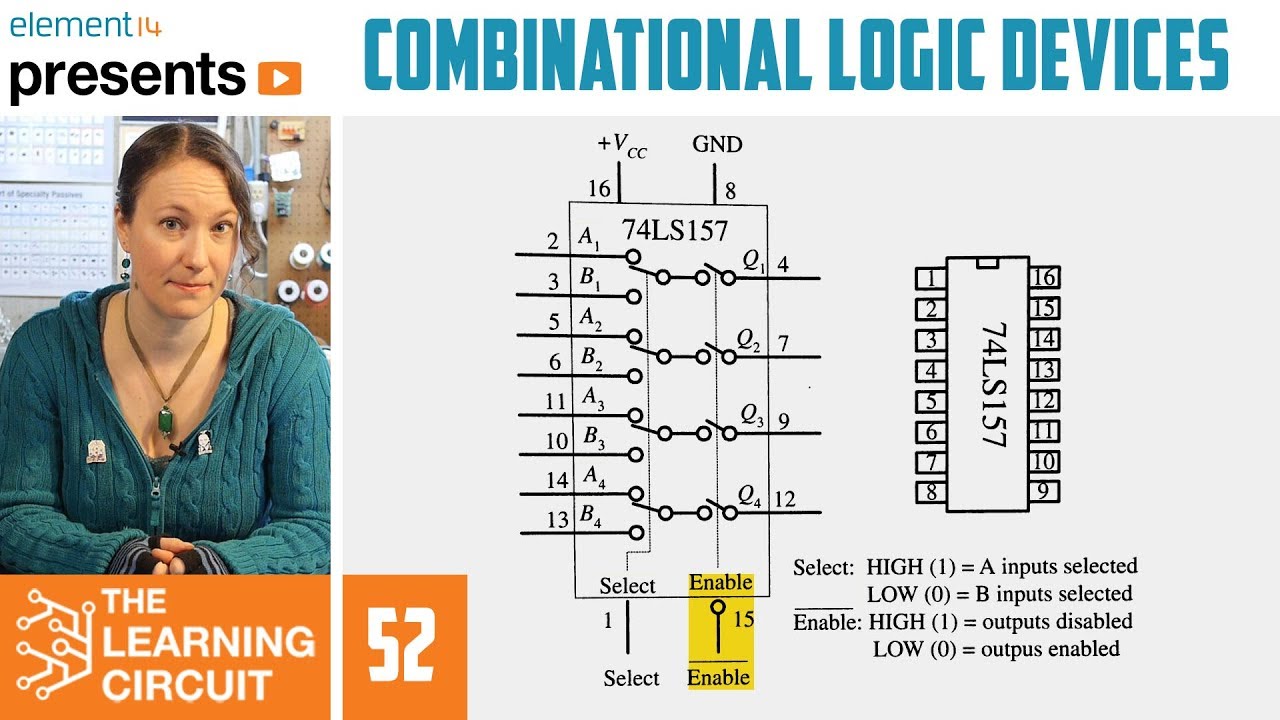
How Combinational Logic Devices Work - The Learning Circuit
5.0 / 5 (0 votes)
