Ep 028: Boolean Expressions, Circuits, and Truth Tables
Summary
TLDRIn this lesson, the instructor explains how to convert a Boolean expression into a circuit diagram, a schematic, and then a truth table. By using basic logic gates—AND, OR, and NOT—the instructor demonstrates step-by-step how to evaluate a given Boolean expression, ensuring a clear understanding of precedence and operations. The Boolean expression involves a combination of inverses, AND operations, and OR operations, with each step illustrated via circuit creation and a corresponding truth table. The lesson also highlights the importance of order of operations and provides clarity on logical gates' functions, preparing students for future lessons on specialized gates like decoders.
Takeaways
- 😀 The lesson focused on converting boolean expressions to circuit diagrams and truth tables.
- 😀 Boolean expressions use three primary gates: NOT, AND, and OR, which have distinct behaviors in logic circuits.
- 😀 In a NOT gate, the input is inverted, and the output is the opposite of the input.
- 😀 An AND gate requires all inputs to be 1 for the output to be 1, represented with a dot symbol.
- 😀 An OR gate requires only one input to be 1 for the output to be 1, represented with a plus sign.
- 😀 The order of operations in boolean expressions follows similar rules to algebra, with parentheses, inverses, AND operations, and then OR operations.
- 😀 The NOT operation behaves like parentheses, affecting the entire expression under the bar.
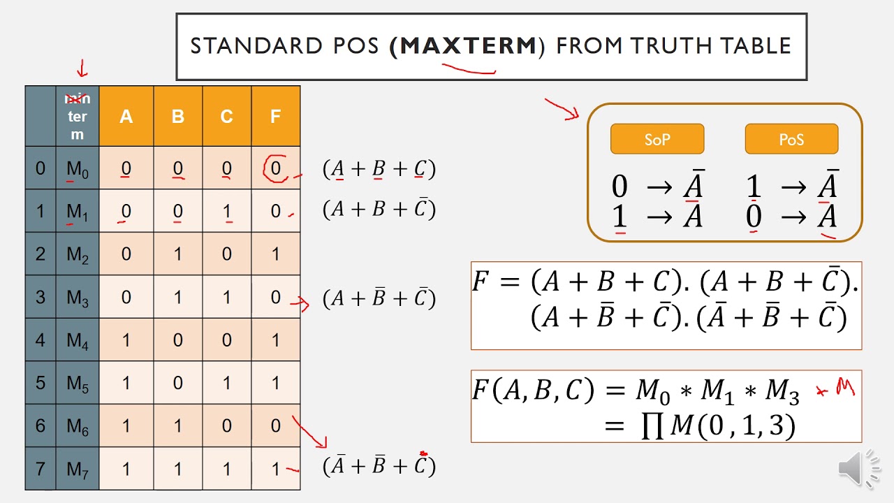
- 😀 The truth table lists every possible combination of input values (0s and 1s) and calculates the corresponding output.
- 😀 In the example expression, the NOT operations (inverses) of inputs are computed first, followed by AND and OR operations.
- 😀 The truth table helps visualize how inputs propagate through the gates, showing the output for every combination of inputs.
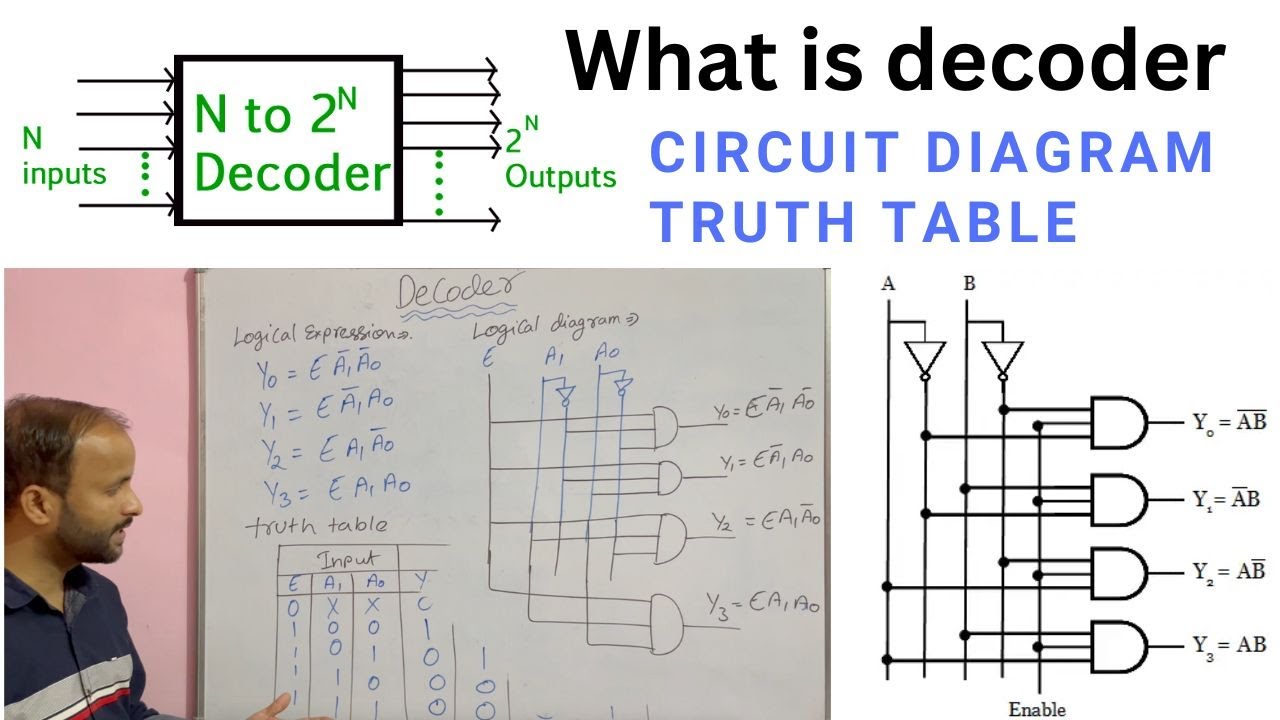
- 😀 The lesson also previews the next topic: a decoder gate, which is a special type of AND gate used to identify specific conditions when all inputs are true.
Q & A
What was the main topic of the previous lesson discussed in the transcript?
-The main topic was converting between a boolean expression (in boolean algebra) to a circuit diagram using gate symbols and creating a truth table.
What are the three primary gates mentioned in the lesson?
-The three primary gates discussed are the NOT gate (inverter), the AND gate, and the OR gate.
How is the NOT gate represented and what does it do?
-The NOT gate is represented with a bar over a variable (such as a bar over 'A') and it inverts the value of the variable, changing 1 to 0 and vice versa.
What is the difference between the AND and OR gates?
-The AND gate requires all inputs to be 1 for the output to be 1, while the OR gate requires only one input to be 1 for the output to be 1.
What is the order of operations for boolean expressions?
-The order of operations in boolean expressions is: first, handle any parentheses (which are represented by the bar in the NOT gate), then perform AND operations (multiplication), and lastly, perform OR operations (addition).
Why is boolean algebra simpler than regular algebra?
-Boolean algebra is simpler because there are only two possible values: 0 and 1, as opposed to the infinite set of numbers in regular algebra.
What was the first step in drawing the circuit diagram from the boolean expression?
-The first step was identifying the input signals, which were 'A', 'B', and 'C', and drawing them to represent the variables in the circuit.
How are AND operations prioritized in the boolean expression?
-AND operations are prioritized over OR operations in the boolean expression, meaning the AND gates are computed before OR gates in the process.
What does the 'hoppy thing' in older circuit diagrams represent?
-The 'hoppy thing' in older diagrams was used to represent a wire crossing over another without making a connection. This has mostly been replaced in modern diagrams with clearer CAD representations.
What is the role of the decoder gate that will be discussed in the next lesson?
-The decoder gate is a special type of AND gate that is used to identify when all of its inputs are true, which is useful in specific logical operations like identifying one particular condition in a system.
Outlines

Dieser Bereich ist nur für Premium-Benutzer verfügbar. Bitte führen Sie ein Upgrade durch, um auf diesen Abschnitt zuzugreifen.
Upgrade durchführenMindmap

Dieser Bereich ist nur für Premium-Benutzer verfügbar. Bitte führen Sie ein Upgrade durch, um auf diesen Abschnitt zuzugreifen.
Upgrade durchführenKeywords

Dieser Bereich ist nur für Premium-Benutzer verfügbar. Bitte führen Sie ein Upgrade durch, um auf diesen Abschnitt zuzugreifen.
Upgrade durchführenHighlights

Dieser Bereich ist nur für Premium-Benutzer verfügbar. Bitte führen Sie ein Upgrade durch, um auf diesen Abschnitt zuzugreifen.
Upgrade durchführenTranscripts

Dieser Bereich ist nur für Premium-Benutzer verfügbar. Bitte führen Sie ein Upgrade durch, um auf diesen Abschnitt zuzugreifen.
Upgrade durchführenWeitere ähnliche Videos ansehen

Ep 027: Deriving a Truth Table from Combinational Logic

CMOS NAND Gate Explained: Circuit, Working, Implementation, and Truth Table

[Part 1] Unit 1.2 - Boolean Functions
Product of Sum (POS) expression
Explain Decoder with Truth Table | Circuit Diagram | Logical Expression in Digital electronics
Eletrônica Digital #65: Simplificando Expressão Lógica Booleana (Exercício)
5.0 / 5 (0 votes)
