1st order modelling 8 - tank level system
Summary
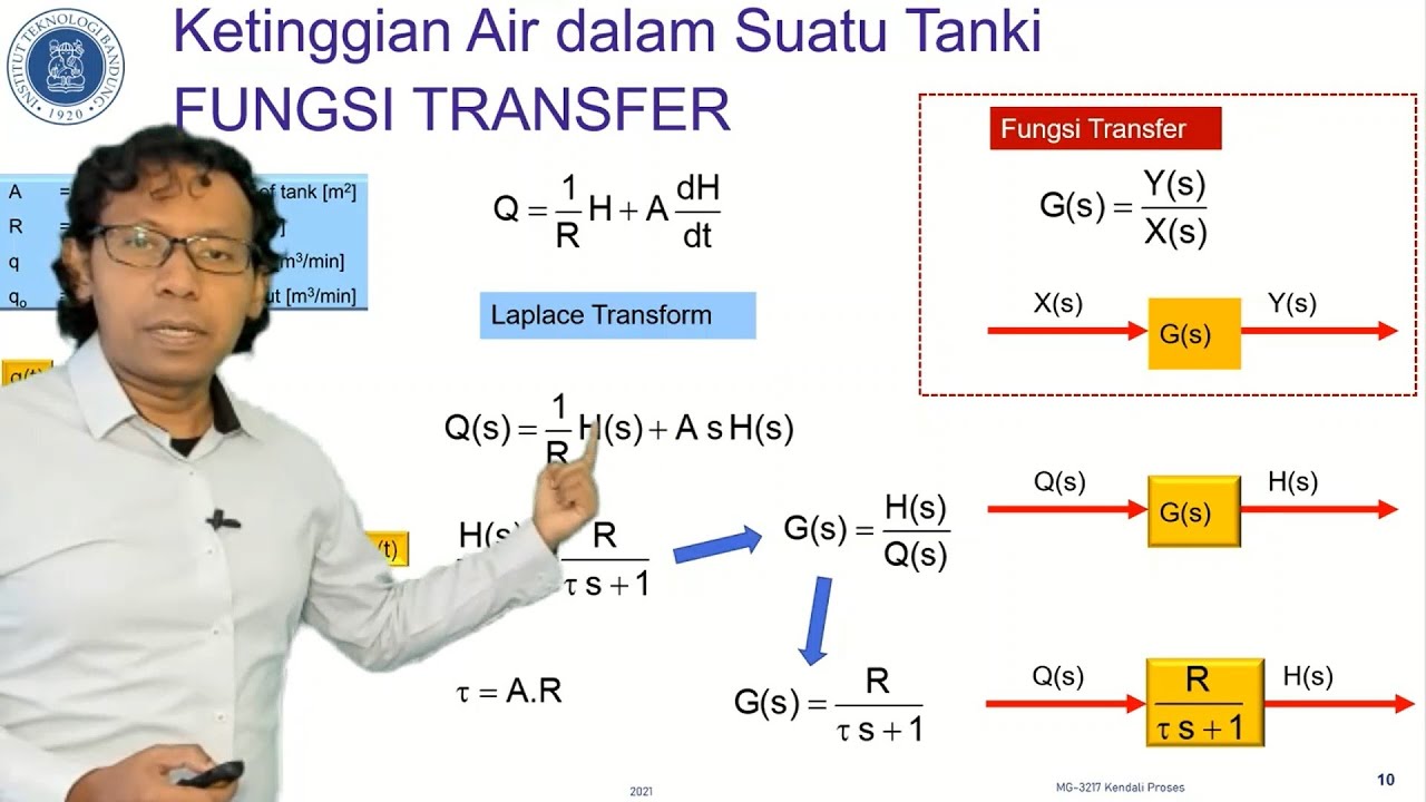
TLDRThis video explores the modeling of tank level systems, which are common in the process industry. It covers the relationship between fluid depth, inflow, and outflow, using a simple tank example. The video explains how flow-out is determined by pressure differences, and how the rate of change in fluid volume is influenced by these flows. The tank's behavior is modeled using a first-order differential equation, with a focus on time constant and resistance. Key takeaways include how increasing cross-sectional area slows fluid changes and how resistance affects the time constant and steady-state depth.
Takeaways
- 😀 Tank level systems are common in the process industry and important to model for understanding fluid behavior.
- 😀 A simple tank model assumes flows in and out, and a specific fluid depth (H) in the tank.
- 😀 The relationship between depth, flow in, and flow out is critical for understanding tank behavior.
- 😀 Flow out depends on the pressure difference between the tank and the outlet pipe, which is governed by the fluid's depth (H).
- 😀 The pressure at the bottom of a tank can be approximated as ρgh, where ρ is the fluid density, g is gravity, and h is the depth.
- 😀 The flow through the restriction at the outlet pipe is dependent on the pressure difference, simplified to a constant R in the model.
- 😀 For uniform cross-sectional area tanks, the rate of change of volume is related to the rate of change of depth (dh/dt).
- 😀 The flow rate in and flow rate out balance to determine the rate of change in volume (dV/dt).
- 😀 The final model for depth in the tank is derived as A * dh/dt + Rg * H = FN, where A is the cross-sectional area.
- 😀 By dividing through by Rg, the model is converted into time constant form with time constant T = A / Rg and a steady-state gain of 1 / (Rρg).
- 😀 Increasing the tank's cross-sectional area (A) increases the time constant, meaning the tank will fill/empty slower, while increasing Rρg slows the behavior and decreases the steady-state gain.
Q & A
What is the main focus of this video?
-The video focuses on modeling tank level systems, specifically exploring how the depth of a tank depends on the flow in and out, and how the flow out depends on the tank's depth.
What is the key assumption made about the tank in this model?
-The model assumes a simple tank with a flow coming in and a flow going out, and a specific depth of fluid denoted as H.
How does the flow out of the tank depend on the depth?
-The flow out of the tank depends on the pressure difference between the bottom and top of the tank, which is related to the depth H of the fluid.
What is the relationship between the flow through a restriction and pressure difference?
-The flow through a restriction is determined by the pressure difference (P1 - P2) between the two ends of the restriction. In this case, the pressure difference is approximated by the formula row * g * H, where row is the fluid density, g is acceleration due to gravity, and H is the depth of the fluid.
What is the role of the constant 'R' in the flow out equation?
-The constant 'R' represents factors such as the cross-sectional area and material properties of the outlet pipe, influencing the flow rate out of the tank.
What does the equation A dh/dt represent in the context of the tank?
-The equation A dh/dt represents the rate of change of the depth (dh/dt) in the tank, where A is the cross-sectional area of the tank.
What equation models the depth in the tank after considering the flow in and out?
-The equation for the depth in the tank is A dh/dt + R row g * H = FN, where FN is the flow rate in, R is a constant, row is the fluid density, g is acceleration due to gravity, and H is the depth of the fluid.
How does the time constant form of the model look after transformation?
-After transforming the model, it takes the time constant form: T dh/dt + H = k * FN, where the time constant T is A / (R * row * g), and the gain is 1 / (R * row * g).
How does the cross-sectional area (A) affect the time constant of the system?
-If the cross-sectional area (A) is increased, the time constant increases, meaning the rate at which the tank fills or empties slows down.
What happens when the resistance to flow (R * row * g) is increased?
-Increasing the resistance to flow (R * row * g) will also increase the time constant and the steady-state gain, making the system slower to fill or empty.
Outlines

Dieser Bereich ist nur für Premium-Benutzer verfügbar. Bitte führen Sie ein Upgrade durch, um auf diesen Abschnitt zuzugreifen.
Upgrade durchführenMindmap

Dieser Bereich ist nur für Premium-Benutzer verfügbar. Bitte führen Sie ein Upgrade durch, um auf diesen Abschnitt zuzugreifen.
Upgrade durchführenKeywords

Dieser Bereich ist nur für Premium-Benutzer verfügbar. Bitte führen Sie ein Upgrade durch, um auf diesen Abschnitt zuzugreifen.
Upgrade durchführenHighlights

Dieser Bereich ist nur für Premium-Benutzer verfügbar. Bitte führen Sie ein Upgrade durch, um auf diesen Abschnitt zuzugreifen.
Upgrade durchführenTranscripts

Dieser Bereich ist nur für Premium-Benutzer verfügbar. Bitte führen Sie ein Upgrade durch, um auf diesen Abschnitt zuzugreifen.
Upgrade durchführen


5.0 / 5 (0 votes)
