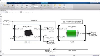
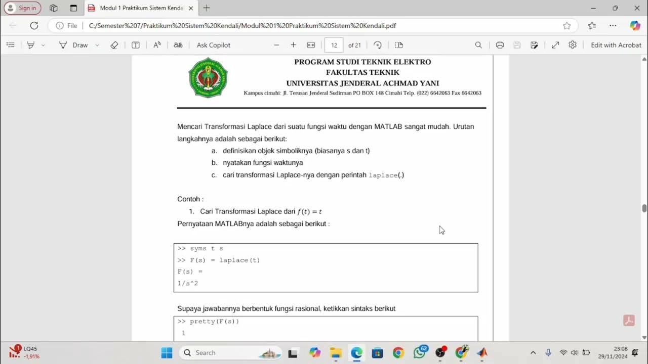
MATLAB - SIMULINK (1). SISTEM KENDALI (Part 28)
Summary
TLDRThe transcript provides an instructional overview on using Simulink, a simulation and model-based design environment, primarily for system control applications. It explains how to simulate dynamic systems using graphical block diagrams and libraries, particularly in older versions of the software. The video details steps such as creating models, adding blocks for input and output, and simulating the behavior of systems like motor control. Additionally, the video covers real-time system verification, error detection, and visualization of results through an oscilloscope display, aiming to provide hands-on guidance for understanding system dynamics.
Takeaways
- 😀 Simulink is used for simulating dynamic systems and supports model-based design.
- 💻 The script focuses on how to use Simulink, integrated with MATLAB, for system control simulation.
- 🔧 Simulink uses a block diagram approach with a customizable library for simulating systems.
- 📊 The script emphasizes using transfer functions to represent system control within Simulink.
- 🛠 Simulink enables automatic code generation, real-time system testing, and verification for embedded systems.
- 📂 It provides various blocks from the library that can be dragged and used to model and simulate control systems.
- 📈 Signal generators and scopes (oscilloscopes) are used to visualize output in the system simulation.
- ⚙️ Simulink can also detect errors in models and alert users, aiding in debugging system designs.
- 📡 The script demonstrates how to connect blocks for signal input and output, and visualize them using Scopes.
- 🚀 The final outcome of running a Simulink simulation is the graphical display of system behavior, especially for dynamic controls.
Q & A
What is the main focus of the video script?
-The video script focuses on how to use Simulink, a simulation environment integrated with MATLAB, to simulate control systems, build models, and analyze dynamic systems.
What is Simulink and how does it integrate with MATLAB?
-Simulink is a simulation and model-based design environment for dynamic systems, integrated with MATLAB. It provides a graphical block diagram interface and a library of customizable blocks to simulate, test, and analyze control systems and other models.
What are the key features of Simulink mentioned in the script?
-The key features include a block diagram environment, libraries for different types of blocks, real-time testing, automatic code generation (C, Verilog), and the ability to simulate control systems and embedded systems.
How does Simulink help in simulating control systems?
-Simulink allows users to design, test, and simulate control systems by connecting blocks that represent input signals, transfer functions, and outputs. It also provides real-time simulation and verification tools to test system functionality.
What role does the 'Library Browser' play in Simulink?
-The 'Library Browser' in Simulink provides access to various blocks needed to build models, such as sources, sinks, math functions, and control blocks. These blocks can be dragged into the model to simulate different system components.
What is a 'Transfer Function' and how is it used in Simulink?
-A 'Transfer Function' represents the relationship between the input and output of a control system. In Simulink, users can insert a Transfer Function block to model this relationship and simulate how the system responds to inputs.
What is the significance of 'real-time simulation' in Simulink?
-Real-time simulation allows the model to interact with real-world inputs and outputs, making it possible to test and verify embedded systems in real-time conditions before deployment.
What are the steps to create a basic simulation in Simulink?
-To create a basic simulation, users first open Simulink, access the Library Browser, select and connect necessary blocks like sources, transfer functions, and sinks, and then run the simulation to see the output in graphical form, such as through an oscilloscope block.
What tools are mentioned for visualizing simulation outputs?
-The script mentions using an oscilloscope ('Scope' block in Simulink) to visualize the output signals in real-time. The scope graphically displays the waveforms generated by the simulation.
What challenges are highlighted in understanding Simulink without hands-on practice?
-The script suggests that understanding Simulink through theory alone can be difficult. Hands-on practice, such as building and simulating models in Simulink, is essential for better comprehension.
Outlines

Dieser Bereich ist nur für Premium-Benutzer verfügbar. Bitte führen Sie ein Upgrade durch, um auf diesen Abschnitt zuzugreifen.
Upgrade durchführenMindmap

Dieser Bereich ist nur für Premium-Benutzer verfügbar. Bitte führen Sie ein Upgrade durch, um auf diesen Abschnitt zuzugreifen.
Upgrade durchführenKeywords

Dieser Bereich ist nur für Premium-Benutzer verfügbar. Bitte führen Sie ein Upgrade durch, um auf diesen Abschnitt zuzugreifen.
Upgrade durchführenHighlights

Dieser Bereich ist nur für Premium-Benutzer verfügbar. Bitte führen Sie ein Upgrade durch, um auf diesen Abschnitt zuzugreifen.
Upgrade durchführenTranscripts

Dieser Bereich ist nur für Premium-Benutzer verfügbar. Bitte führen Sie ein Upgrade durch, um auf diesen Abschnitt zuzugreifen.
Upgrade durchführenWeitere ähnliche Videos ansehen

Simulink Control Systems and PID, Matlab R2020b

How to Make Simulation of Inverted Pendulum (Balancing Robot) Control in Simulink Matlab

How to Design Load Frequency Control using Simulink ? | Dr. J. A. Laghari

How To Design Automatic Voltage Regulator (AVR) Model of Power System in MATLAB/SIMULINK Software ?

Battery Management System Development in Simulink

Modul A1 Demo Praktikum Sistem Kendali
5.0 / 5 (0 votes)
