Image Sensors 6 of 6 - Charge Movement in CCD
Summary
TLDREl script del video explica detalladamente la estructura superior de metales en un CCD (Dispositivo de Acople de Carga), un sensor de imagen a base de silicio. Se ilustra cómo se desplaza la carga en una matriz de CCD, mostrando cómo se captura y traslada la carga (electrones) de píxel en píxel hasta un capacitor y luego a un amplificador. Se describen las fases de reloj involucradas y la importancia del aislamiento por óxido de silicio entre los metales y el silicio para evitar conexiones DC no deseadas que podrían afectar el funcionamiento del CCD. Se compara el proceso de traslado de carga con la analogía de una 'fila de cubeta', destacando la necesidad de un óxido de alta calidad para el buen funcionamiento del dispositivo.
Takeaways
- 📷 El script habla sobre la estructura superior de metales en un CCD (Dispositivo de Acople de Carga), que es un sensor de imagen a base de silicio.
- 🔍 Se describe cómo se mueve la carga en un array de CCD, utilizando un diagrama de un array de silicio CCD de 4x4 píxeles.
- 🔧 Se explica el proceso de mover una carga (electron) a través de los píxeles hasta que alcanza un capacitor y luego un amplificador.
- 🌐 Se menciona la importancia de la capa de óxido entre los metales y el silicio, que evita una conexión directa DC y permite el paso de carga.
- 🔩 Se describen las tres fases de metal (fase 1, fase 2 y fase 3) asociadas con cada píxel y su papel en el movimiento de la carga.
- 🔋 Se ilustra cómo se configuran las fases de metal con diferentes voltajes para capturar y mover electrones dentro del píxel.
- 🚫 Se enfatiza que los electrones no pueden pasar a través del óxido hacia el metal, lo cual es crucial para la lectura de la señal.
- 🔄 Se compara el funcionamiento del CCD con una 'fila de cubeta', donde la carga se transfiere de un píxel a otro de manera controlada.
- 🛠️ Se resalta la necesidad de una buena calidad del óxido para evitar daños y mantener la separación entre el metal y el silicio.
- ⚠️ Se señala que un daño en la capa de óxido puede causar problemas graves, como la pérdida de electrones o la inserción de agujeros, afectando el funcionamiento del CCD.
Q & A
¿Qué es un CCD y qué función cumple?
-Un CCD, o Dispositivo de Acoplo de Carga, es un sensor de imagen a base de silicio que captura imágenes visibles. Funciona mediante la manipulación de carga eléctrica para transmitir y almacenar información de imagen.
¿Cómo se organiza la estructura de un array de CCD?
-El array de CCD está compuesto por una serie de píxeles organizados en una rejilla, como el ejemplo de 4x4 que se menciona en el guion, con 16 píxeles en total.
¿Qué es el propósito del registro de desplazamiento serial en un CCD?
-El registro de desplazamiento serial es una fila de un píxel de altura que tiene el mismo número de píxeles que el array superior. Se utiliza para mover la carga eléctrica, como un electrón, hacia un capacitor y luego hacia un amplificador.
¿Cómo se mueve la carga en el array de CCD hacia el capacitor?
-La carga se mueve de píxel en píxel dentro del array, utilizando fases de reloj diferentes para manipular la carga hasta que alcance el capacitor.
¿Cuántas fases de metal tiene cada píxel en el ejemplo básico del CCD?
-En el ejemplo básico proporcionado, cada píxel tiene asociadas tres fases de metal distintas que no se tocan entre sí y que facilitan el paso de carga entre ellos.
¿Por qué es importante que las fases de metal no se toquen entre sí?
-Las fases de metal no se tocan para permitir el paso de carga entre ellas sin una conexión directa continua, lo que es crucial para el funcionamiento del CCD.
¿Cómo se logra que un electrón se capture en un píxel específico?
-Se configuran las fases de reloj con diferentes voltajes para atraer el electrón hacia la fase con el potencial más alto, que en el ejemplo es +9V, y rechazarlo de las fases con potenciales más bajos.
¿Qué sucede si un electrón se encuentra en un potencial de -9V en el silicio?
-Un electrón tendría tendencia a moverse lejos del potencial de -9V y hacia un potencial más alto, como +9V, en busca del potencial más alto dentro del sistema.
¿Cómo se describe el proceso de transmisión de carga en un CCD utilizando la analogía de la 'fila de cubos'?
-La analogía de la 'fila de cubos' compara cada fase del reloj en cada píxel con una persona con un cubo. Las personas (o fases) pasan su contenido al siguiente cubo (píxel) hasta que toda la carga (electrones) es recolectada y transmitida.
¿Por qué es crucial que la oxidación del silicio en un CCD sea de alta calidad?
-La calidad de la oxidación del silicio es fundamental para evitar conexiones DC no deseadas entre el metal y el silicio subyacente, lo que podría causar problemas graves en el funcionamiento del CCD, como la pérdida de carga o la inserción de corriente.
Outlines
📐 Estructura de metales en CCD: Introducción
El primer párrafo introduce el tema del video, que es la estructura de metales en un CCD (Charge Couple Device), un sensor de imagen basado en silicio. Se describe cómo se mueve la carga en una matriz de CCD y se presenta un dibujo de una matriz de 4x4, que es un arreglo de 16 píxeles. Se menciona la importancia de los metales en la captura y transferencia de carga, y se detalla cómo se separan estos metales por una capa de óxido para evitar conexiones DC directas con el silicio. El objetivo es explicar cómo se captura y traslada la carga eléctrica a través de la matriz de píxeles.
🔋 Funcionamiento de la transferencia de carga en CCD
Este párrafo se enfoca en el proceso de transferencia de carga en un CCD. Se describe cómo se captura una carga (electron) en un píxel específico y cómo se mueve esta carga a través de las fases del reloj (fases 1, 2 y 3) para ser transmitida fuera del dispositivo. Se ilustra cómo se establecen las fases con diferentes voltajes (+9V, -9V) para guiar la carga a través de los píxeles y se compara con la analogía de una cadena de cubos, donde cada fase del reloj es una persona con un cubo que pasa su contenido al siguiente. Se enfatiza la importancia de la calidad del óxido que separa los metales del silicio para evitar conexiones DC que podrían causar problemas en el funcionamiento del CCD.
⚠️ Importancia de la calidad del óxido en CCD
El tercer párrafo destaca la importancia de una buena calidad del óxido en los CCD. Se explica que el óxido debe ser un buen aislante para evitar que haya una conexión DC entre los metales y el silicio subyacente. Se discute el problema que se presenta si el óxido se daña y permite una conexión DC, lo que puede resultar en la pérdida de carga (electrones y/o huecos) y afectar negativamente el rendimiento del sistema. Se resalta que para que los CCD funcionen correctamente, es esencial tener un óxido de alta calidad que mantenga la separación entre el metal y el silicio.
Mindmap
Keywords
💡CCD
💡Estructura de metal
💡Matriz de silicio
💡Píxeles
💡Carga
💡Fases de reloj
💡Óxido de silicio
💡Amplificador
💡Conexión DC
💡Capacitancia
Highlights
Introduction to the top-level metal structure in a Charge Coupled Device (CCD).
Explanation of a silicon-based image sensor and how charge is shuttled out in a CCD array.
Visual representation of a 4x4 pixel array in a CCD.
Importance of the serial shift register in a CCD and its relation to the pixel array.
Process of moving an electron from one pixel to another in the CCD array.
Illustration of the silicon structure and the P and N type boundaries in a pixel.
Description of the metal layers on top of the pixel and their distinct roles.
Function of the oxide layer in separating metal electrodes from the silicon.
Role of the three metal phases associated with each pixel in charge transfer.
Mechanism of capturing an electron in pixel one using clock phases.
Shuttling of charge between different pixels using controlled clock voltages.
Explanation of how electrons are contained within the silicon during charge transfer.
Importance of maintaining a separation between metal and silicon for proper CCD operation.
The role of silicon dioxide in providing capacitive coupling for charge transfer.
The Bucket Brigade analogy for understanding the charge transfer process in CCDs.
Necessity of high-quality oxide to prevent DC connection between metal and silicon.
Potential issues arising from damaged oxide leading to DC short circuits.
Consequences of DC short circuits on the performance and reliability of CCDs.
Transcripts
in this video I'm going to talk a little
bit about the top level metal structure
in a CCD and a charge couple devices a
visible image sensor a silicon based
image sensor in a previous video I drew
out a silicon CCD array and showed how
charge gets shuttled out I'm going to
redraw it
here okay so we're going to have the
array the array try to draw it a little
slower so lines are more defined and to
have
pixels
pixels and then more in this
direction draw it out okay this is a 4x4
array of pixels 16 pixels there are four
pixels
oops four pixels in this Dimension or
pixels and four pixels in this Dimension
let me number them uh well I won't
number them let's say we had an
electron here oh I forgot the serial
shift
register it's one pixel
high and it has an equal number of
pixels to the array that's above
it let's say we want this electron to
come out to this
capacitance and then
amplifier we know from the previous
video that we first had to move it into
this
pixel and then we move it into this
pixel okay and then we move it into this
pixel okay and then we move it
here we move it
here we move it here then finally out
onto the capacitor well how does that
happen
let me redraw this uh in a in a
different dimension I'm going to label
the pixels here so there's pixel
one pixel 2 and pixel 3 I'm going to
scroll
down in the Silicon let me draw the
Silicon there's one
side there's the other
side
so we can just draw the NP boundary
remember the P type VI is usually much
thicker than the N type so there's n
there's P
type this remembers usually but not
always
grounded okay let's look at what goes on
in a pixel so if you remember from a
previous video that there is
metal metal in on top of the pixel
separated by
oxide and let me draw that I I'll I'll
start drawing and I'll and I'll talk as
I draw on top of each pixel there's a
set each pixel in the basic case has
three metal phases associated with it
and
draw start drawing this out these are
metal notice that this this metal here
is distinct from this metal here which
is distinct from this metal here and
they're not touching each other okay
that's an important point
there's that
metal or
metal you notice this kind of this
structure
oops that
section
metal there's an overlapping structure
and that's so they can pass char charge
between them and this goes on to the end
of the
array just draw that going off to
Infinity
okay what we have uh with this metal oh
it's separated from the underlying
silicon by oxide so I'm going to sketch
with green everywhere there's
oxide
oide it fills in the gaps between
there's no connection no DC connection
between these metal
electrodes filling
in everywhere with
oxide there's oxide even
here so this is
oxide and if I have the right
color this is
metal let me draw the pixel
let's say one
pixel just imaginary
it's there another
pixel is there we'll label this is pixel
one this is pixel 2 and this is pixel 3
let me scroll back up so you can see
what I was talking about pixel one pixel
2 and pixel 3
we want to hand the charge off between
the different
pixels let's say there's an electron
that Finds Its way in the system and we
want to capture it in pixel
one well what you would usually do let
me get back to the right
color we would call
this phase
one clock phase one this
is Phase 2 2 phase 3 each pixel has
three phases in this basic example and
then it repeats just Phase 1 Phase
2 phase
3 phase 1 and so on 1 2 3 1 2 3 1 2 3
Let's make Phase 2 equal to + 9 Vols
phase 3 is equal to Min - 9 Vols and
Phase 1 is equal to-
9
Vol now if you're an
electron sitting in the Silicon let's
say you you you get created down here
and you're going to go to somewhere
within this pixel where are you going to
go well you're going to try to go to The
Highest Potential from the system the
plus 9 volts so you swim of here and you
find yourself right there
okay why aren't you going to sit here
well that potential the potential right
above you there is minus 9 volts so you
don't want to sit there why aren't you
going to sit here well it's the same
thing the potential above you is min - 9
volts and you'd rather be sitting near
the plus 9V potential so that's where
you go and you're captured there you're
stuck you cannot pass through the oxide
to that metal electrode and that's good
because we want to read you out later uh
and you just sit there until we do
something with you well let's do
something with you let me backtrack a
little
bit okay that electron is sitting
there now let's start shuttling you
out let's go back
to this color so let's leave Phase 1 at
Min - 9 Vols Phase 2 will remain at plus
5 Vols and actually something I forgot
to write this phase one is equal to this
phase one so this is also at minus 9
volts
let's change phase three instead of
being minus 9 Vol let's make it+ 9 Vol
now you as an electron you don't care
whether you're where you are whether
you're here whether you're here whether
you're here whether you're here because
anywhere in this stretch here you're
very close to the plus 9 volts and you
like that because that's the highest
potential in the system you don't like
the minus 9 volts that you see here and
you don't like Theus 9 volts that you
see here so you're free to swim about
and anywhere between those two phases of
the clock me backtrack my
colors
so let's say that now instead of this
Phase 2
being plus 9 volts I change it
to minus 9 Vol now you as an electron
are in a situation very similar to what
you were in the
beginning uh what you saw in the
beginning you don't like the minus 9
Vols you want to get away from Theus 9
Vols you want to go towards the plus 9
volts so you move out of this pixel and
over to this
guy and this electron is now captured
underneath this clock phase which is at
plus 9 volt and its nearest Neighbors on
on one side it has minus 9 volts and it
doesn't like that on the other side it
also has - 9 Vols and it doesn't
like and
you can see that what you can do because
these electrodes are overlapping you can
shuttle this charge in in a similar
pattern all the way out the device
between each clock phase in a very
controlled
fashion an important point is that this
electron is contained within the Silicon
as it shuttles along and I mentioned
this it it it can't get through that
oxide in the normal case it can't get
through that ox oide into that metal and
that's good because if it went into the
metal uh we wouldn't be able to read it
out as a signal it would just be part of
the current that that metal is pulling
out of the Silicon we want there to be a
separation between the metal and the
underlying silicon uh which the oxide
provides and we want there also be
enough dialectric coupling enough
capacitive coupling between the two so
that uh uh you don't have to use extreme
clock voltages to shuttle this charge
along to create the kind of
electrostatic effects in Silicon that
needed to shuttle this out and silicon
dioxide also provides
that an analogy that often gets drawn
for the CCD is the Bucket Brigade
Bucket
Brigade analogy and for the Bucket
Brigade analogy you can imagine each one
of these clock phases phase one phase
two phase two phase three in each pixel
being a different person with a bucket
so pixel one has one person
two
people three
people and then the next pixel also has
three
people three people and they each have a
bucket they each have a
bucket and they take turns pouring their
contents into the next person's
bucket until all of the water or
electrons are collected and and red out
and the way we make these uh bucket
transitions happen in the CCD is by
playing with the clock phase voltages
which the clocks the metal clock lines
are separated from the underlying
silicon by the Silicon dioxides there's
no DC connection between the silicon and
this and the metal incidentally uh one
thing that is necessary for the system
to operate properly is that this oxide
is in fact a good oxide and it doesn't
have a contact with the underlying
silicon it doesn't allow a connection
ction between the metal and the
underlying silicon and the DC SS and
sometimes that's doesn't happen
sometimes the oxide gets damaged so
let's say there's a damage point and
then for whatever reason maybe the metal
spikes into the Silicon metal spikes
into the Silicon or some other effect
happens so that now there's a DC
connection between the silicon and this
metal up above what happens then well
that's a big problem because uh it
results in either electrons and hole
and/or holes being sucked out or pushed
in depending on the phase of this clock
so since there's DC connection a DC
short now in this guy let's say it was
at I don't know plus 9 Vol where this
terminal down here is at Ground well
you're going to suck a lot of electrons
out through that guy the effective in
and you are pushing current this way and
that will cause all sorts of nasty
effects with your system and so a
necessary requirement for ccds to
function well is that this oxide is of
very high quality
تصفح المزيد من مقاطع الفيديو ذات الصلة
Image Sensors 3 of 6 - CCD and CMOS Overview 1
Types of Image Sensors | Image Sensing
practica electroscopio Universidad Militar Nueva Granda
Paneles Solares Explicados - ¡Descubre los Misterios del Funcionamiento de los Paneles Solares!
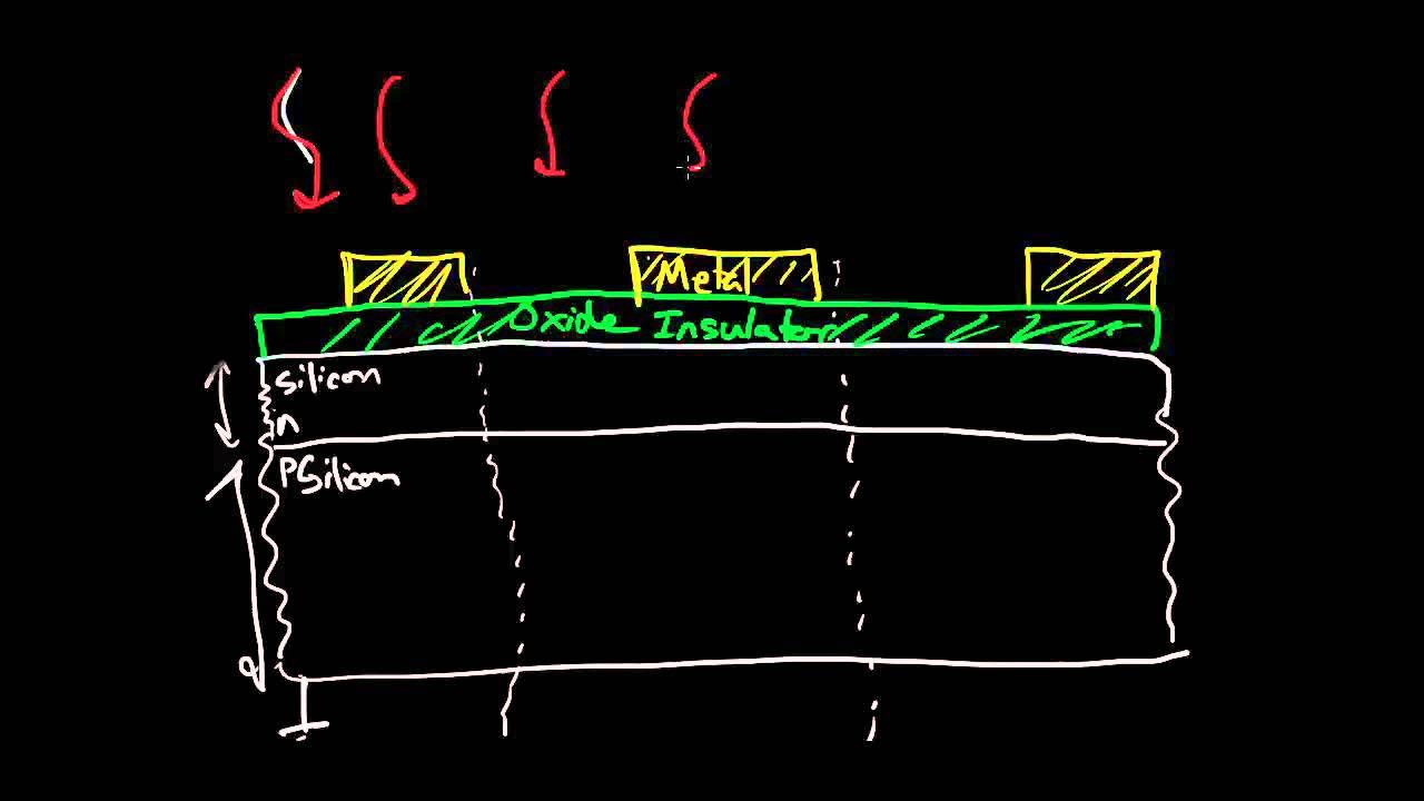
Image Sensors 5 of 6 - Frontside and Backside Illumination
🔌 Cómo se produce LA CORRIENTE ELÉCTRICA [ FLUJO DE ELECTRONES ] 💡
5.0 / 5 (0 votes)