Understanding Engineering Drawings
Summary
TLDRThis video script provides an in-depth guide to understanding engineering drawings, essential tools for engineers to communicate design and manufacturing specifications. It covers the different types of drawings, including assembly, detail, layout, and interface control drawings, and their adherence to standards like ASME Y14 and ISO. The script explains the structure of drawings, projection methods, and the importance of views, dimensions, and tolerances. It also touches on advanced concepts like geometric dimensioning and tolerancing (GD&T), and hints at future trends like model-based definition and statistical tolerance analysis. The video aims to equip viewers with the skills to decipher and effectively use technical drawings in engineering.
Takeaways
- 🔍 Technical drawings are essential tools for engineers to communicate design and manufacturing details.
- 📐 There are different types of engineering drawings, such as assembly, detail, layout, and interface control drawings, each serving specific purposes.
- 📜 Drawings follow conventions defined in standards like ASME Y14 and ISO, with companies often having their own requirements.
- 🏢 The title block, usually at the bottom right, contains vital information like company logo, drawing title, number, scale, and author details.
- 👷♂️ Detail drawings provide all the information needed to fabricate and inspect a specific part, without defining manufacturing methods.
- 📈 Primary views, including front, side, and top views, are key to defining a part's geometry in three dimensions through orthographic projection.
- 🌐 Projection methods differ between first angle and third angle projection, with the latter being more common in North America.
- 📊 Additional views like isometric and exploded views can enhance clarity, while sectional views reveal internal geometry.
- 📝 Drawings often include tables, notes, and bills of materials to provide extra information and instructions.
- 📏 Dimensions on a drawing provide all the necessary measurements for part manufacturing, with best practices guiding their placement and presentation.
- ⚙️ Threads are specified using standardized systems like ISO for metric and Unified Thread Standard for U.S. customary units, detailing diameter, pitch, and fit class.
- 🔄 Tolerances define acceptable deviations from nominal sizes and are crucial for part inspection and acceptance, with best practices advocating for as宽松 as necessary.
Q & A
What is the primary purpose of technical drawings in engineering?
-Technical drawings are used to define how a part should be manufactured and inspected, as well as to explain how different parts of a system fit together. They serve as essential communication tools for engineers.
What are the different types of engineering drawings mentioned in the script?
-The script mentions assembly drawings, detail drawings, layout drawings, and interface control drawings. Assembly drawings show how components fit together, detail drawings define the geometry of a single component, layout drawings illustrate a design approach without much detail, and interface control drawings identify interfaces with other components.
What are the common standards that drawings often follow?
-Drawings often follow conventions defined in technical standards such as ASME Y14 and various ISO standards. These standards provide detailed guidelines that companies typically adhere to, with some having their own specific requirements.
What is the general structure of a drawing according to the script?
-A drawing generally has a title block, a revision history table, and the drawing space. The title block is usually located at the bottom right corner and contains important information such as the company logo, drawing title, drawing number, scale, and details about the author, checker, and approver.
Can you explain the concept of primary views in technical drawings?
-Primary views in technical drawings include the front, side, and top views. They are created by projecting the visible edges of the part onto an imaginary plane aligned with the face of the object, a method known as orthographic projection. These views are essential for defining a part in three dimensions.
What is the difference between third angle projection and first angle projection?
-Third angle projection arranges views based on the projection plane being placed between the camera and the object, with the left view placed to the left of the front view and the top view above it. First angle projection places the projection plane behind the object, resulting in the left view being placed to the right of the front view and the top view below it.
What is an isometric view and how does it differ from primary views?
-An isometric view is an additional view that shows the object in three dimensions, which can improve the clarity of a drawing. Unlike primary views, which are aligned and show the object from specific orthogonal directions, isometric views provide a more intuitive representation of the object's shape.
What is the purpose of a bill of materials in assembly drawings?
-A bill of materials in assembly drawings is a table that lists the parts that make up the assembly and the required quantities. It serves as a reference to identify and quantify the components used in the assembly.
What are some best practices to consider when dimensioning a drawing?
-Best practices for dimensioning include placing dimensions outside the part, not using hidden lines for dimensioning unless necessary, avoiding dimensioning 90-degree angles as they can be assumed, and adding centerlines to circular features to aid in dimensioning and clarity.
What is the purpose of geometric dimensioning and tolerancing (GD&T)?
-Geometric dimensioning and tolerancing (GD&T) is a method for applying tolerances that allows for the control of a range of different characteristics such as flatness, roundness, and perpendicularity. It complements traditional dimensional tolerancing by considering the function and shape of an object, not just its size.
What does the script suggest about the future of engineering drawings and design?
-The script suggests that the future of engineering drawings and design may involve model-based definition and statistical tolerance analysis. These topics indicate a shift towards more sophisticated and data-driven approaches in engineering design.
Outlines

هذا القسم متوفر فقط للمشتركين. يرجى الترقية للوصول إلى هذه الميزة.
قم بالترقية الآنMindmap

هذا القسم متوفر فقط للمشتركين. يرجى الترقية للوصول إلى هذه الميزة.
قم بالترقية الآنKeywords

هذا القسم متوفر فقط للمشتركين. يرجى الترقية للوصول إلى هذه الميزة.
قم بالترقية الآنHighlights

هذا القسم متوفر فقط للمشتركين. يرجى الترقية للوصول إلى هذه الميزة.
قم بالترقية الآنTranscripts

هذا القسم متوفر فقط للمشتركين. يرجى الترقية للوصول إلى هذه الميزة.
قم بالترقية الآنتصفح المزيد من مقاطع الفيديو ذات الصلة
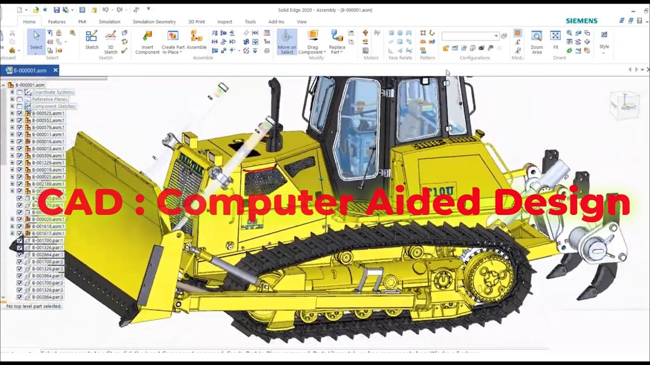
What is Computer Aided Design ?
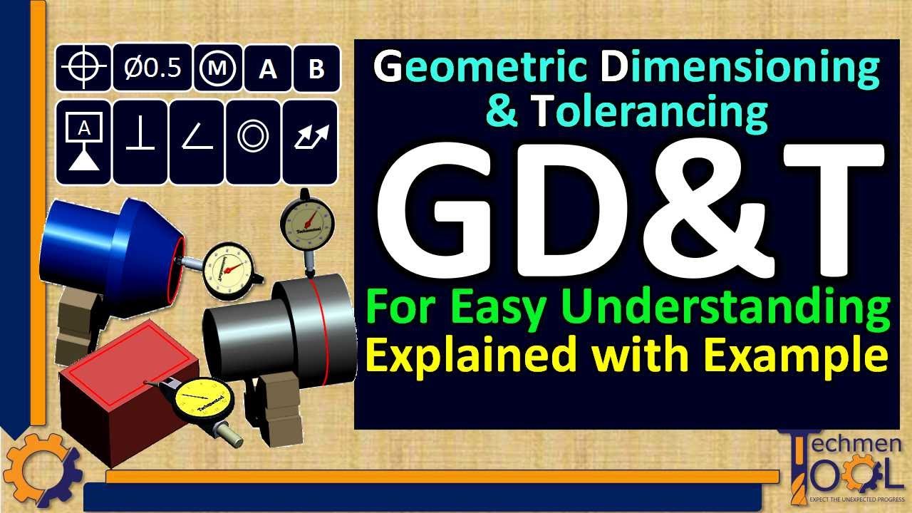
What is GD&T? | GD&T symbols Explained with Example | for Beginners Understanding | Subscribe Us
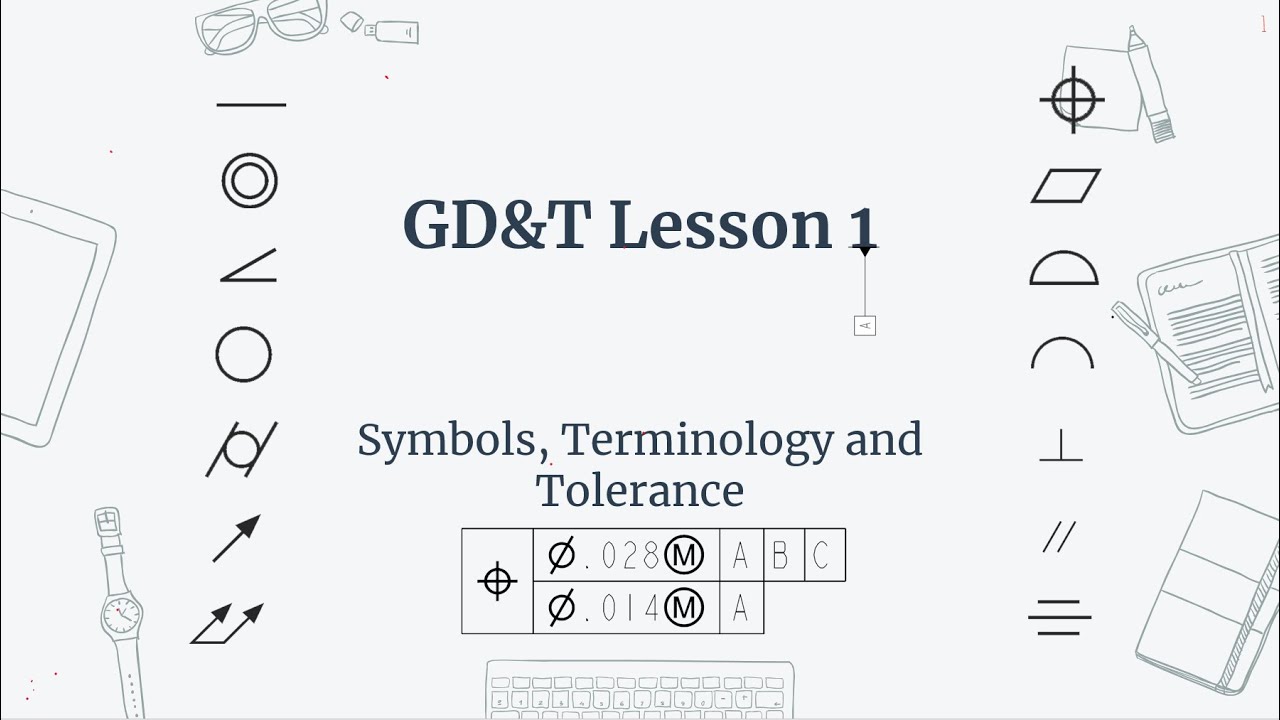
GD&T Lesson 1: Symbols, Terminology and Tolerance.

What Are The Tender Documents In Construction Projects
Materi PKK kelas XI (KD 3.6/4.6): Gambar Kerja Untuk Pembuatan Prototype Produk Barang/Jasa

Types of Pictorial Drawings
5.0 / 5 (0 votes)
