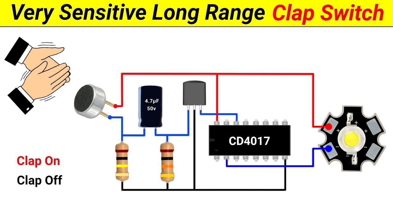
Belajar dan Membuat Sensor Suara untuk menyalakan Peralatan Listrik di Rumah | Project Sederhana
Summary
TLDRThis video guides viewers through the process of building a series of electronic circuits, including a microphone signal conversion circuit using a BC547 transistor, a monostable multivibrator with an NE555 timer IC, and a decade counter with the IC 4017. The circuits demonstrate fundamental concepts in electronics such as sound-to-electric signal conversion, timing, and sequential output control. The final application showcases how to control a lamp using these circuits, providing a practical and engaging demonstration of the components in action. Ideal for those with intermediate knowledge of electronics.
Takeaways
- 😀 The script explains how to build a simple electronic circuit using a condenser microphone, resistors, an NPN transistor (BC547), and ICs (NE555 and 4017).
- 😀 The condenser microphone converts sound frequencies into electrical signals.
- 😀 Two resistors (39kΩ and 470Ω) control the flow of current, with the 39kΩ resistor enabling the transistor to activate when sound is detected.
- 😀 The BC547 NPN transistor acts as a switch, outputting a high logic signal (1) when no sound is detected, and a low logic signal (0) when sound is present.
- 😀 The script explains the working of a monostable multivibrator circuit using the NE555 timer IC, which changes its output from low to high when triggered.
- 😀 The NE555 IC's capacitor charges through a 100kΩ resistor, and once it reaches 2/3 of the supply voltage, the output returns to a low state.
- 😀 The NE555 multivibrator's output high state duration is influenced by how long the capacitor takes to charge.
- 😀 The IC 4017 is a counter IC with 10 outputs, alternating between high and low logic states when triggered by an input pulse at pin 14.
- 😀 The IC 4017 shifts between its 10 output states in response to pulses, each state corresponding to a different output pin from Q0 to Q9.
- 😀 The final output shows how the assembled circuit can be connected to a load, such as a lamp, to demonstrate the functioning of the system.
Q & A
What is the purpose of the condenser microphone in the circuit?
-The condenser microphone converts sound into an electrical signal, which is then processed by the surrounding circuitry.
Why is the 39kΩ resistor used in the microphone circuit?
-The 39kΩ resistor is used to limit the current before it reaches the base of the NPN transistor, ensuring that the transistor is properly activated when the sound signal is received.
How does the NPN transistor (BC547) function in the microphone circuit?
-The transistor acts as a switch. When the condenser microphone detects sound, the transistor is activated, causing the output to switch from high to low logic.
What happens when no sound is detected by the microphone?
-When no sound is detected, the transistor remains off, and the output from the transistor stays at high logic (logic 1).
How does the monostable multivibrator circuit (IC 555) work?
-In a monostable configuration, the IC 555 generates a single pulse in response to a low logic input. The output switches from low to high for a set duration based on the capacitor's charging time, then returns to low once the capacitor is fully charged.
What determines the duration of the pulse in the monostable multivibrator circuit?
-The duration of the pulse is determined by the resistor (100kΩ) and the capacitor (10µF). The capacitor charges through the resistor until it reaches 2/3 of the supply voltage, which then causes the output to return to low.
What is the function of pin 6 on the IC 555 in the monostable circuit?
-Pin 6 on the IC 555 is used to monitor the voltage across the capacitor. Once the capacitor charges to 2/3 of the supply voltage, pin 6 triggers the IC to return the output to low.
How does the IC 4017 counter work?
-The IC 4017 is a decade counter with 10 outputs. When a pulse is applied to pin 14, the output shifts from high to low across the 10 outputs in a sequential manner, allowing the counter to track events or generate a series of timing signals.
What is the significance of the 25V power module in the setup?
-The 25V power module is used to provide the necessary voltage for the lamp and other components in the circuit. It powers the system, ensuring that all electronic parts function correctly.
How is the lamp controlled by the circuit?
-The lamp is controlled through a relay or similar switching mechanism that is activated by the outputs from the counter and monostable multivibrator circuits. When triggered, the relay either switches the lamp on or off based on the logic signals from the circuits.
Outlines

هذا القسم متوفر فقط للمشتركين. يرجى الترقية للوصول إلى هذه الميزة.
قم بالترقية الآنMindmap

هذا القسم متوفر فقط للمشتركين. يرجى الترقية للوصول إلى هذه الميزة.
قم بالترقية الآنKeywords

هذا القسم متوفر فقط للمشتركين. يرجى الترقية للوصول إلى هذه الميزة.
قم بالترقية الآنHighlights

هذا القسم متوفر فقط للمشتركين. يرجى الترقية للوصول إلى هذه الميزة.
قم بالترقية الآنTranscripts

هذا القسم متوفر فقط للمشتركين. يرجى الترقية للوصول إلى هذه الميزة.
قم بالترقية الآنتصفح المزيد من مقاطع الفيديو ذات الصلة

Como Fazer um Sequencial de Leds (muito simples)

How to make a Clap Switch || using 4017 IC || Very Sensitive Clap Switch || Science Project

Práctica 9: Circuito integrado 555

D Flip Flop

Prinsip dasar sistem kerja rangkaian boost converter

Off Delay Timer | how to make off delay timer | how to make delay timer | delay timer
5.0 / 5 (0 votes)
