Important parts of 8051 Microcontroller | Accumulator of 8051 | Program Counter of 8051 | 8051
Summary
TLDRThis video lecture delves into the intricacies of the 8051 microcontroller, focusing on key components like the 8-bit ALU that handles arithmetic and logical operations, including single-bit manipulation. It explains the role of the accumulator A, register B for multiplication and division, and the program counter (PC) in instruction execution. The video also covers the data pointer (DPTR) for addressing data in RAM or external memory, the stack pointer (SP) for managing the stack memory, and the program status word (PSW) that reflects the status of the program after each instruction. Examples and further explanations are promised in upcoming videos to clarify these concepts.
Takeaways
- 😀 The 8051 microcontroller's ALU (Arithmetic and Logic Unit) is an 8-bit unit responsible for executing instructions and performing arithmetic and logical operations.
- 🔢 The ALU in the 8051 can perform both 8-bit and single-bit operations, such as adding the accumulator to a register or complementing a specific bit of a port.
- 📦 The accumulator (A) is an 8-bit register that is central to most arithmetic and logical operations in the 8051, often used as the primary operand for these operations.
- 📈 Register B, also 8-bit, is specifically dedicated to multiplication and division instructions in the 8051, storing results in a combined form with the accumulator for 16-bit results.
- 🔄 The program counter (PC) is a 16-bit register that points to the address of the next instruction to be executed in the program memory (ROM).
- 📌 The data pointer (DPTR) is a 16-bit register used to point to data in the data memory (RAM) or external memory, and can also be used for lookup tables in ROM.
- 🔠 The stack pointer (SP) is an 8-bit register that holds the address of the top of the stack in the internal RAM, used for last-in, first-out operations.
- 🔄 The stack memory is used for storing return addresses for subroutines and interrupt service routines, and is pointed to by the stack pointer.
- 📈 The program status word (PSW) is an 8-bit register that reflects the status of the program, such as carry and overflow flags, and can be altered by specific instructions.
- 🔑 The PSW register is bit-addressable, allowing for individual bit manipulation to set or clear specific flags, influencing program control flow.
- 🛠️ The 8051 microcontroller is based on the Harvard architecture, with separate memory spaces for program (ROM) and data (RAM), each pointed to by the PC and DPTR respectively.
Q & A
What is the primary function of the ALU in the 8051 microcontroller?
-The ALU (Arithmetic and Logic Unit) in the 8051 microcontroller is responsible for executing instructions along with performing arithmetic and logical operations. It is an 8-bit unit that can also perform single-bit operations.
What is the significance of the accumulator in the 8051 microcontroller?
-The accumulator, labeled as 'A', is an 8-bit register that is used for most arithmetic and logical operations in the 8051 microcontroller. It is central to the microcontroller's operations as many instructions are executed with respect to the accumulator.
What is the purpose of register B in the 8051 microcontroller?
-Register B in the 8051 microcontroller is an 8-bit register dedicated to multiplication and division instructions. It works in conjunction with the accumulator to store the results of these operations, with B holding the higher byte and A holding the lower byte.
How does the 8051 microcontroller handle multiplication and division results?
-When performing multiplication or division, the 8051 microcontroller stores the result in the accumulator (A) and register B. For multiplication, the 16-bit result is stored with B holding the higher byte and A the lower byte. For division, the quotient is in A and the remainder in B.
What is the role of the program counter (PC) in the 8051 microcontroller?
-The program counter (PC) in the 8051 microcontroller is a 16-bit register that holds the address of the next instruction to be executed. It automatically increments after fetching an instruction, pointing to the subsequent instruction in the program memory.
How is the data pointer (DPTR) used in the 8051 microcontroller?
-The data pointer (DPTR) in the 8051 microcontroller is a 16-bit register that holds the address of data in the data memory, which is RAM. It can also point to external RAM and is used for indexing and accessing lookup tables in ROM.
What is the purpose of the stack pointer (SP) in the 8051 microcontroller?
-The stack pointer (SP) in the 8051 microcontroller is an 8-bit register that holds the address of the top of the stack in the internal RAM. It is used for managing the stack, which operates on a last-in, first-out basis and is crucial for subroutine and interrupt handling.
What is the role of the Program Status Word (PSW) in the 8051 microcontroller?
-The Program Status Word (PSW) in the 8051 microcontroller is an 8-bit register that indicates the status of the program, such as whether a carry or overflow has occurred. It changes after every instruction execution and can also be manually altered by specific instructions.
How does the 8051 microcontroller perform single-bit operations?
-The 8051 microcontroller can perform single-bit operations through its ALU. For example, the instruction 'CPL P0.3' complements a single bit of port 0, demonstrating the ALU's capability to handle one-bit logical operations.
What is the initial address indicated by the stack pointer (SP) after a reset in the 8051 microcontroller?
-After a reset, the stack pointer (SP) in the 8051 microcontroller indicates the address 07h of the internal RAM, which is part of the stack memory area.
How is the 8051 microcontroller's internal RAM structured in relation to the stack pointer (SP)?
-The internal RAM of the 8051 microcontroller has a stack memory area that ranges from 00h to 7Fh in address. The stack pointer (SP), being an 8-bit register, points to this area and is used with push and pop instructions as well as in subroutine and interrupt operations.
Outlines

此内容仅限付费用户访问。 请升级后访问。
立即升级Mindmap

此内容仅限付费用户访问。 请升级后访问。
立即升级Keywords

此内容仅限付费用户访问。 请升级后访问。
立即升级Highlights

此内容仅限付费用户访问。 请升级后访问。
立即升级Transcripts

此内容仅限付费用户访问。 请升级后访问。
立即升级浏览更多相关视频

Internal RAM Structure of 8051 | Bit Addressable Area & General Purpose Area of Internal RAM in 8051

SFRs of 8051 Microcontroller | Features of SFR in 8051 | PSW | DPTR | TMOD | TCON | SCON | PMOD
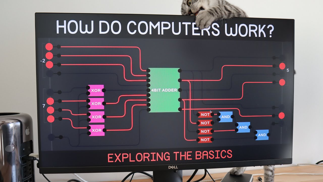
Exploring How Computers Work
How Computers Calculate - the ALU: Crash Course Computer Science #5

CPU - Organisasi dan Arsitektur Komputer

Logical Instructions of 8051 Microcontroller | AND | OR | XOR | CPL | SWAP | Instructions of 8051
5.0 / 5 (0 votes)
