Ep 027: Deriving a Truth Table from Combinational Logic
Summary
TLDRThis lesson walks through the creation of a truth table for an alarm system, explaining how inputs like door sensors, motion detectors, and glass break detectors interact with logic gates to trigger the alarm. The process includes defining Boolean algebraic expressions, constructing a truth table, and using AND and OR gates to model the system. Additionally, the lesson introduces the concept of an inverter in combinational logic, demonstrating how it inverts input signals. By the end, the system's logic is fully represented through its circuit, truth table, and Boolean expression, laying the groundwork for simplifying complex circuits.
Takeaways
- 😀 The lesson focuses on building and analyzing a simple alarm system circuit using combinational logic.
- 😀 The circuit consists of a door sensor, motion detector, and glass break detector.
- 😀 The goal of the alarm system is to trigger the alarm if any sensor detects a breach while the system is armed.
- 😀 The truth table for the circuit is created to represent all possible input combinations of the sensors (D, M, G).
- 😀 There are 16 possible input patterns for the four bits (D, M, G, and a system armed signal).
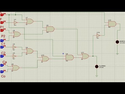
- 😀 The OR gate is the first gate in the circuit, combining inputs D and M, producing an output of 1 if either input is 1.
- 😀 The AND gate processes the result of D OR M, ensuring that both inputs (A and D OR M) must be 1 to output a 1.
- 😀 The final OR gate combines the AND gate output with the G input, ensuring the alarm triggers if either condition is true.
- 😀 The system behaves by outputting 1 (alarm triggers) if any sensor input is active while the system is armed.
- 😀 The inverter concept is introduced, explaining how a signal can be inverted by using a bar notation in Boolean expressions.
- 😀 The lesson emphasizes the importance of understanding Boolean algebra, truth tables, and logic gates in designing circuits efficiently.
Q & A
What was the main objective of the alarm system discussed in the lesson?
-The main objective was to create a system that triggers an alarm when certain conditions are met: the door is open, motion is detected, or glass is broken, when the system is armed.
How many inputs are involved in the alarm system, and what are they?
-The alarm system involves four inputs: D (door), M (motion), G (glass break), and A (armed).
What is the significance of the truth table in this lesson?
-The truth table is used to represent all possible input combinations for the alarm system and determine the corresponding output, which is whether the alarm is triggered or not.
How do you determine the number of rows in a truth table for a system with four binary inputs?
-For four binary inputs, the number of rows in the truth table is 2^4, which equals 16. This represents all possible combinations of zeros and ones for the four inputs.
What operation does the first OR gate perform in the circuit?
-The first OR gate performs the operation of combining inputs D (door) and M (motion) using the logical OR operation, meaning the output will be 1 if either D or M is 1.
What is the role of the AND gate in the alarm system?
-The AND gate combines the output from the first OR gate (D OR M) with the input A (armed). The alarm will only be triggered if both the system is armed (A = 1) and either the door or motion detector is triggered.
What happens in the last OR gate of the circuit?
-The last OR gate takes the output of the AND gate (A AND (D OR M)) and combines it with the input G (glass break). If any of these are 1, the alarm is triggered.
How does the truth table reflect the behavior of the alarm system?
-The truth table shows how the alarm system behaves based on the values of the inputs. When the system is armed, the alarm is triggered if any of the input conditions (door, motion, or glass break) are true. When disarmed, the alarm is triggered only if the glass break (G) input is 1.
Can you explain the concept of an inverter in Boolean logic?
-An inverter in Boolean logic is a gate that flips the input value. If the input is 1, the output is 0, and if the input is 0, the output is 1. This is often represented with a bar over the expression (e.g., A OR B with a bar over it means the inverse of A OR B).
How does an inverter affect the truth table of a logical expression like A OR B?
-For the expression A OR B with an inverter, the truth table would show the inverse of the OR operation. Whenever A OR B is 1, the inverter makes the output 0, and when A OR B is 0, the inverter makes the output 1.
Outlines

此内容仅限付费用户访问。 请升级后访问。
立即升级Mindmap

此内容仅限付费用户访问。 请升级后访问。
立即升级Keywords

此内容仅限付费用户访问。 请升级后访问。
立即升级Highlights

此内容仅限付费用户访问。 请升级后访问。
立即升级Transcripts

此内容仅限付费用户访问。 请升级后访问。
立即升级浏览更多相关视频

Ep 026: Introduction to Combinational Logic

BASIC OF FIRE ALARM SYSTEMS ( DASAR-DASAR SISTEM DETEKSI KEBAKARAN) - PART 6
Ejercicio de compuertas lógicas en protoboard, Alarma y Marcha de un automóvil
What is a Fire Alarm System?

Cara membuat alarm pintu dan jendela sederhana tapi kualitas mantap

System alarmowy, kurs, szkolenie, programowanie, podłączenie, Satel CA-5, alarm
5.0 / 5 (0 votes)
