Certified SolidWorks Associate (CSWA) Sample Exam Exercise
Summary
TLDRThis SolidWorks tutorial walks through the creation of a 3D part by demonstrating key features such as plane selection, sketching, extrusion, cuts, and hole features. The tutorial explains how to define dimensions, apply constraints, and create symmetrical designs. It includes detailed instructions for creating complex geometries, counterbore holes, tapered angles, and extruded cuts, along with tips for adjusting the geometry for optimal results. This step-by-step guide is perfect for those looking to build their skills in SolidWorks and gain hands-on experience with basic and advanced features.
Takeaways
- 😀 Start by selecting the *Right Plane* for your sketch to match the geometry.
- 😀 Set the dimensions of the base geometry (180mm length, 22mm height, 22mm depth) to begin creating the shape.
- 😀 Apply a 55° angle between the two lines to define the geometry precisely.
- 😀 Use the *Extruded Boss/Base* feature with a 90mm width for symmetry in both directions.
- 😀 Add a 6mm deep cutout with a 23mm width, positioned 115mm from the edge of the model.
- 😀 Create a new plane at a 25° angle to sketch the next set of features, including a circle with a 28mm radius.
- 😀 Use *Extruded Boss/Base* again, setting the end condition to *Up to Next* for the new feature.
- 😀 For counterbore holes, use the *Hole Wizard* tool, with a 22mm diameter and 12mm depth for the counterbore.
- 😀 Add additional cutouts with specific dimensions, like the 28mm width and 5mm depth, using the *Extruded Cut* feature.
- 😀 Maintain symmetry when creating final cutouts by using construction lines and applying smart dimensions.
- 😀 Use *Extruded Cut* for the last cuts, applying the *Up to Next* condition for accurate material removal.
Q & A
What is the first step in the SolidWorks exercise?
-The first step is to select the 'Right Plane' as the starting plane, as it aligns with the geometry of the design.
What are the dimensions used for the initial extruded shape?
-The dimensions for the initial extruded shape are 180 mm for length, 125 mm for height, 90 mm for width, and 22 mm for depth.
Why is the 'Midplane' option used in the extrude feature?
-The 'Midplane' option is used to make the geometry symmetrical, as it extrudes the shape evenly in both directions from the center plane.
What is the purpose of the 'Extruded Cut' feature in SolidWorks?
-The 'Extruded Cut' feature is used to cut through the model, removing material along a selected profile, such as the 20 mm depth cut mentioned in the tutorial.
How is a counterbore hole created in the exercise?
-A counterbore hole is created using the 'Hole Wizard' feature. The diameter is set to 22 mm with a counterbore diameter of 45 mm, and the depth is set to 12 mm. The hole is then positioned at a specified location on the model.
What feature is used to create a tapered cut with a 30° angle?
-A corner rectangle is drawn, and a symmetric constraint is applied. The cut is then created using the 'Extruded Cut' feature with a depth of 5 mm and a tapered angle of 30°.
What does the 'Up to Next' option in the 'Extruded Cut' feature do?
-The 'Up to Next' option in the 'Extruded Cut' feature ensures that the cut stops at the next available surface, making the cut more precise and targeted.
How is symmetry achieved in the tapered cut feature?
-Symmetry is achieved by applying a 'Center Line' and using the 'Symmetric' smart dimension to align the elements evenly on either side.
What is the significance of the 'Reverse Direction' option when using the 'Extruded Cut' feature?
-The 'Reverse Direction' option allows users to change the direction of the cut, ensuring it goes in the correct direction when the default cut direction is incorrect.
How does the exercise use the 'Hide' feature, and why is it important?
-The 'Hide' feature is used to hide planes after they are no longer needed. This helps declutter the workspace, making the model easier to view and work with.
Outlines

此内容仅限付费用户访问。 请升级后访问。
立即升级Mindmap

此内容仅限付费用户访问。 请升级后访问。
立即升级Keywords

此内容仅限付费用户访问。 请升级后访问。
立即升级Highlights

此内容仅限付费用户访问。 请升级后访问。
立即升级Transcripts

此内容仅限付费用户访问。 请升级后访问。
立即升级浏览更多相关视频
SolidWorks - Tutorial for Beginners in 13 MINUTES! [ COMPLETE ]

Computer Mouse Surface Modelling in Creo 3.0 | Creo Beginner Tutorial 2021

SOLIDWORKS Extrude Cut Feature
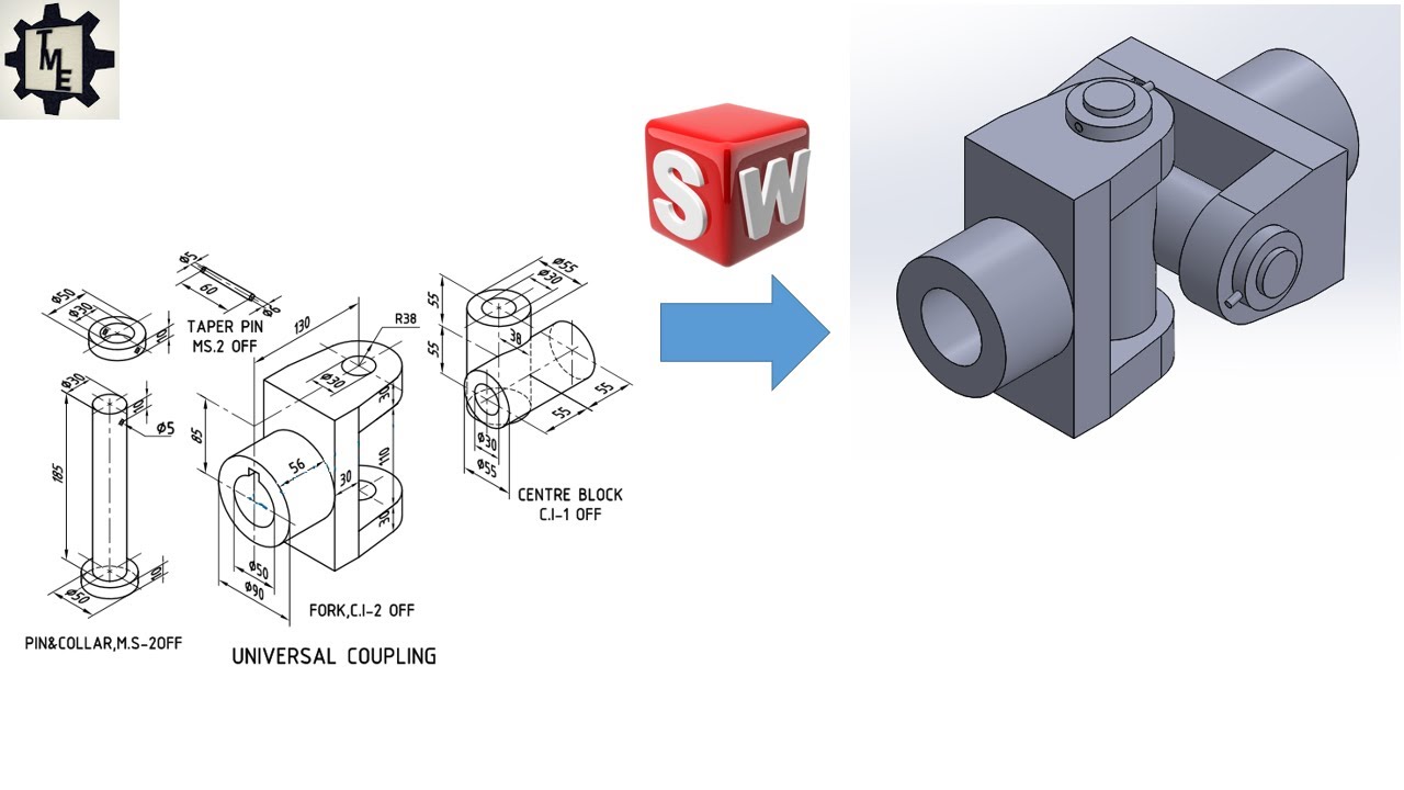
Universal Coupling using SOLIDWORKS | Part and Assembly Modelling | Tutorials for beginners
First Look at SOLIDWORKS Software - SOLIDWORKS

Blender 3D Tutorial Membuat Karakter Game Amoung Us! 3D Modeling, (Pemula) Blender 2.90
5.0 / 5 (0 votes)
